Intersection Equipment Installation Instructions
52
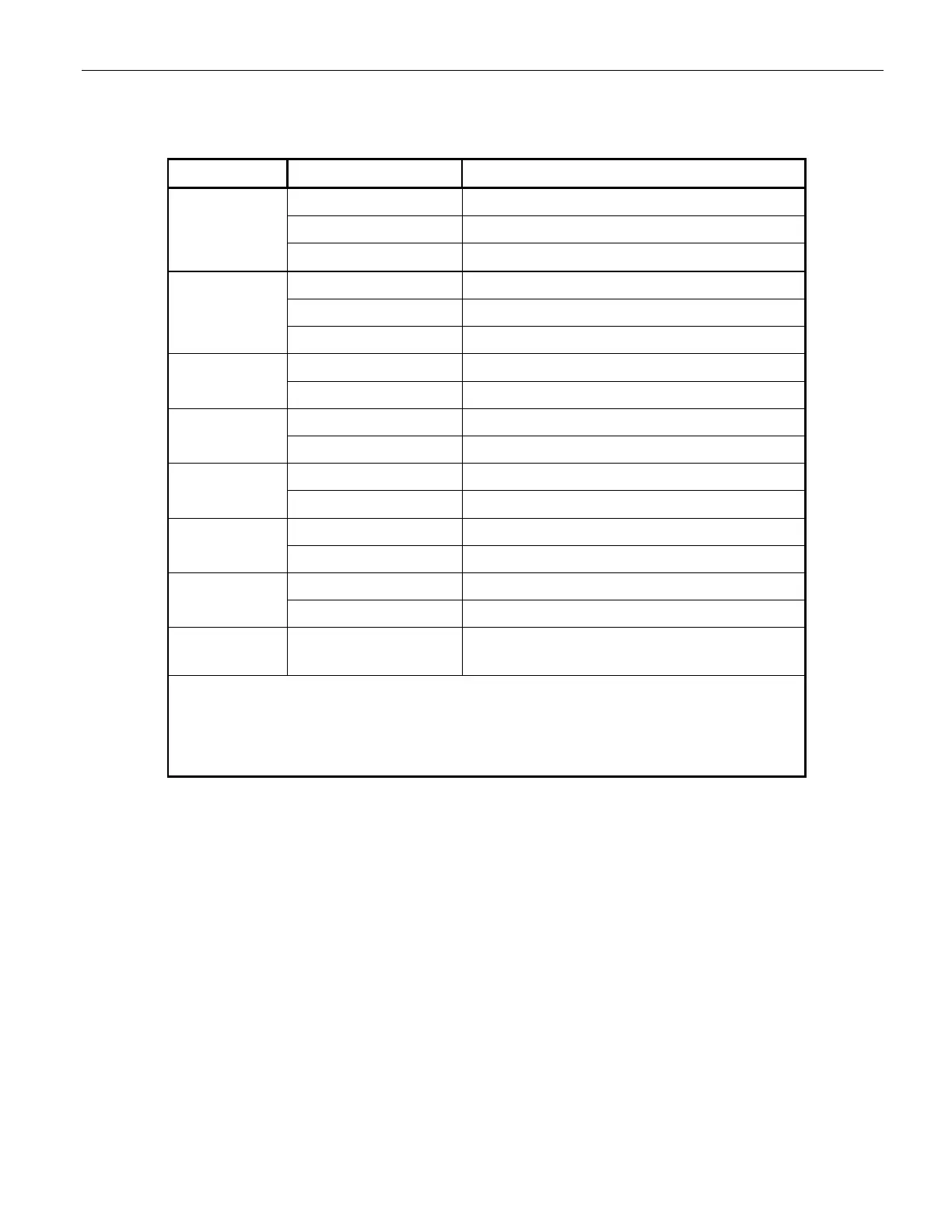
Table 13-1 lists the LED indicators on the front panel of the phase selector, the color or condition of the
LED, and what it means.
Indicator Color or Condition Meaning
STATUS Off Phase selector powered off or offline
Steady Green Phase selector powered and online
Flashing Green Phase selector in standby mode
RADIO Off** Radio/GPS unit not connected
Amber Radio/GPS unit connected no GPS lock
Green Radio/GPS unit connected with GPS lock
LINK Off** No other radios in range
Green Actively communicating with another radio
A High* High priority call on channel A
Low* Low priority call on channel A
B High* High priority call on channel B
Low* Low priority call on channel B
C
High* High priority call on channel C
Low* Low priority call on channel C
D
High* High priority call on channel D
Low* Low priority call on channel D
A, B, C, D All on steady amber Phase selector in broken mode, contact tech
support
* Flashing indicator means the call is present, but the output is
pending.
** The radio and link indicators will always be off if the phase
selector is operating in IR only mode.
Table 13-1 Phase Selector Indicators