Intersection Equipment Installation Instructions
62
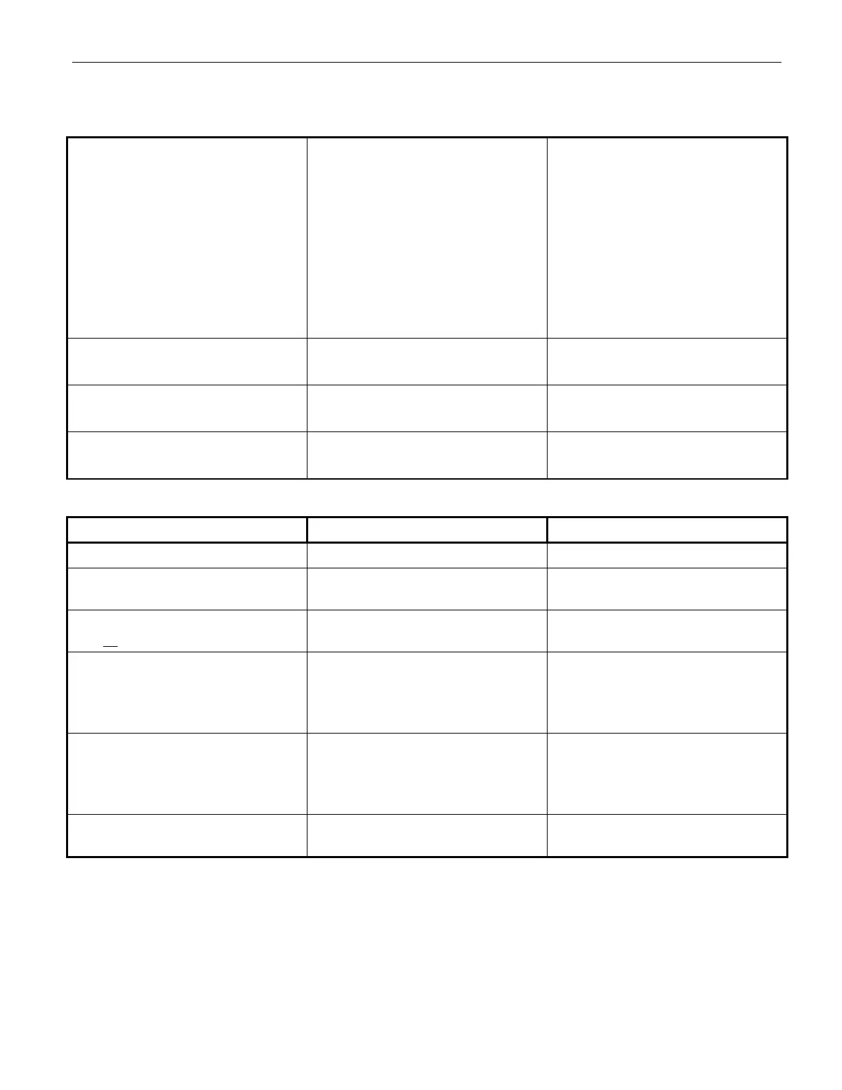
Table 15-1 Troubleshooting Symptoms, Possible Causes, and Solutions (continued)
Location/Terminal Expected Voltage Notes
Black/White wires into card rack 120 VAC
Pins A and B on card edge
connector
24 VDC To power phase selector.
Green LED inside Model 1040
Rev A card rack (Power Supply)
On Check fuse if LED is off.
24 VDC terminal on front of
phase selector
Approximately 21 VDC
(When power applied through
card edge connector)
Check fuse.
External 24 VDC attached to this
terminal may also be used to
power phase selector.
Brown to Brown/White Approximately 8.3 VDC GPS power source, check for at
least 5 seconds.
Powered even when phase
selector is switched off.
Violet to Violet/White Approximately 9.0 VDC Radio power source, check for at
least 5 seconds.
Table 15-2 Expected Voltages
Intersection alternates displaying
and dropping the left turn arrow
when approaching vehicle has left
turn signal activated.
Vehicle brake light bulb shared
with turn signal indication.
Emergency flashers are active.
Driver is using turn signals to
indicate lane changes
Controller or phase selector not
programmed correctly.
Reconnect vehicle turn signal
sense lines to front turn signal
wires.
Turn of emergency flashers
Avoid using turn signals for lane
changes
Reprogram controller or phase
selector.
Active Greens window shows all
greens active continuously.
Green Sense AC neutral (AC–) not
connected.
Connect green sense common
(white wire) to cabinet common.
All channel call LEDs on steady Phase selector in broken mode Contact tech support
LEDs continue to cycle through
power-up sequence
Check detector wiring for short
circuit