Intersection Equipment Installation Instructions
70
7. Connect the harness plug to the round connector on the card rack front panel.
8. Connect the Model 1012 or Model 1010 Radio GPS unit to the phase selector. See section 3 for
details.
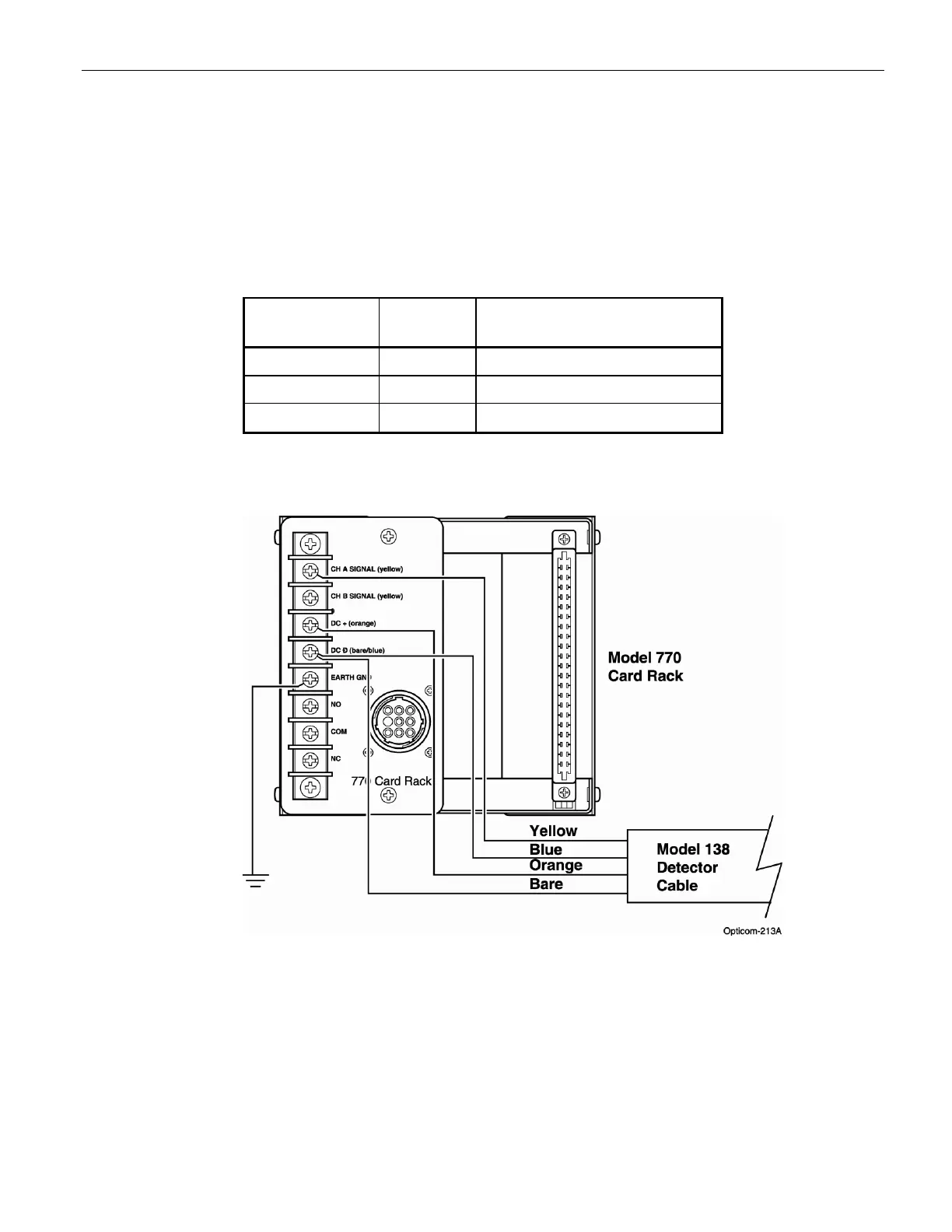
9. If you are using IR detectors, connect the detectors to the card rack per figure 20-2. See the
711/721/722 detector installation instructions for details on connecting the wires inside of the detector.
A Model 770 card rack must be used if you are connecting IR detectors. A Model 1045 card rack has
no connection points for IR detectors.
Wire
Color
Pin
Number
Function
Black 1 115 VAC (Hot, AC+)
White 2 AC Neutral (Common, AC–)
Green 3 Chassis/earth ground
Table C-1. Model 770 and 1045 Harness Wiring
Figure C-2 IR detector connections to a 770 gate opener card rack
Notes:
• When operating in GPS mode, Intersection/Gate Opener equipment will not operate until setup
and mapping procedures are completed. Refer to the On-site software Help files for details on
how to set up and map the equipment.
• Only rear outputs 1 and 2 are connected to the relay, be sure to use one of these outputs when
configuring the phase selector.