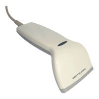
Opticon
OPR 3001
Specifications Manual
9
Conditions
Barcode Sample: OPTOELECTRONICS Test Sample
PCS: 0.9
Resolution: 0.25 mm
Symbology: 9-digit Code-39
Quiet Zone: 10 mm
N/W Ratio: 1:2.5
Distance: 100 mm from the edge of scanner
Angle: α = 0° β = 15° γ = 0°
Curvature: R = ∞
Power supply voltage: 6.0 V
Direct light or specular reflection light from a source should be prevented from entering
the acceptance area.
Note: α, β and γ respectively represent pitch, skew and tilt. Please see section 7 for how
these values are defined.
5. Electrical Specifications
5.1. Electrical Characteristics
Parameter Symbol Min Typ Max Unit Remarks
5.4 6.0 6.6 V RS-232C
Power supply voltage
4.5 5.0 5.5 V USB and Wedge
— 96 130 mA RS-232C when emitting
Operating current
I
OP
— 90 125 mA USB and Wedge when emitting laser
— 400 600 mA RS-232C
Rush current
I
PEEK
— 300 500 mA USB and Wedge
— 35 60 mA RS-232C
Stand-by current
I
PRE
— 30 55 mA USB and Wedge
Conditions:
• Connect 1Ω resistance to a power supply line in series and measure the
current by the voltage between both ends of resistance.
• Power supply voltage is measured at a connector terminal area.
• The current value depends on the host computer to which the device is
connected.
 Loading...