b. Insert connector C into the right slide rail until it locks into place with an audible click [2
and 3].
c. Gently tug on the right side of the CMA back slide bar to verify that connector C is
properly seated.
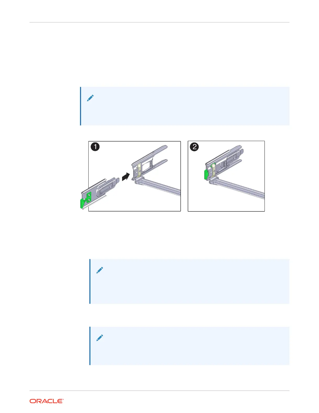
5. To prepare CMA connector D for installation, remove the tape that secures the slide rail
latching bracket to connector D, and ensure that the latching bracket is properly aligned
with connector D [1 and 2].
Note:
The CMA is shipped with the slide rail latching bracket taped to connector D. You
must remove the tape before you install this connector.
6. To install CMA connector D into the left slide rail:
a. While holding the slide rail latching bracket in place, insert connector D and its
associated slide rail latching bracket into the left slide rail until connector D locks into
place with an audible click [1 and 2].
Note:
When inserting connector D into the slide rail, the preferred and easier
method is to install connector D and the latching bracket as one assembly
into the slide rail.
b. Gently tug on the left side of the CMA back slide bar to verify that connector D is
properly seated.
Note:
The slide rail latching bracket has a green release tab. Use the tab to release
and remove the latching bracket so that you can remove connector D.
Chapter 4
Replacing the Cable Management Arm
4-24