ST 9100 - HARDWARE GUIDE
2.3 Connectors
Transceiver 24 position mating connector Chogori Technology Company
Satellite Antenna IMS Connector Systems
3400.SMBA.2K10.089 (RG58/LMR-195 sized cable)
FAKRA - K-curry yellow
Cellular Antenna IMS Connector Systems
3400.SMBA.2D10.029 9RG174 sized cable)
FAKRA - D-bordeaux
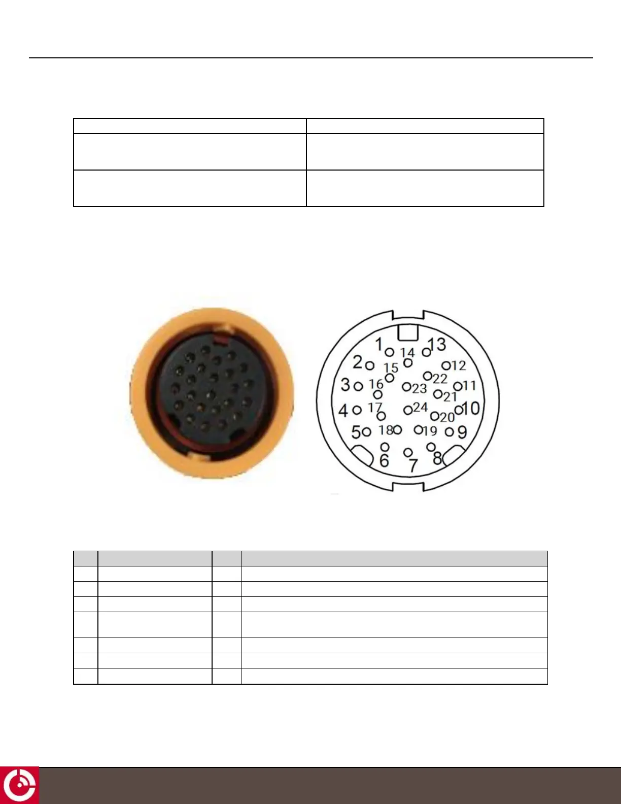
2.3.1 Connector Pin Assignment
Table 3 maps to the layout shown in Figure 10.
Figure 10: Transceiver View of Connector
Table 3: Electrical Pin Assignment
Note: CAN0 is available for BETA trials.
PIN Function Type Description
1 RS485_A I/O Half duplex RS485 driver output or receiver input (complementary to RS485_B)
2 Digital_IN4 / 0-5 V_IN4 I Digital input or 0-5 V
3 Digital_IN3 / 0-5 V_IN3 I Digital input or 0-5 V
4 I/O_4 I/O Multifunction GPIO, push-pull, analog input, current limited current sink and
ignition load
5 I/O_2 I/O Multifunction GPIO, push-pull, analog input and current sink
6 Ground PWR External supply ground return
7 External Voltage PWR External 9-32 VDC supply
T413, Version 0.04 BETA © ORBCOMM
®
Proprietary
18