ST 9100 - HARDWARE GUIDE
Simplified block diagrams of the I/O when configured as digital inputs, digital outputs, and analog inputs are shown
in the figures below (Figure 11, Figure 12, and Figure 13).
The transceiver also supports two dedicated outputs (Output_5 and Output_6). More information on these outputs
can be found in section 2.3.1.
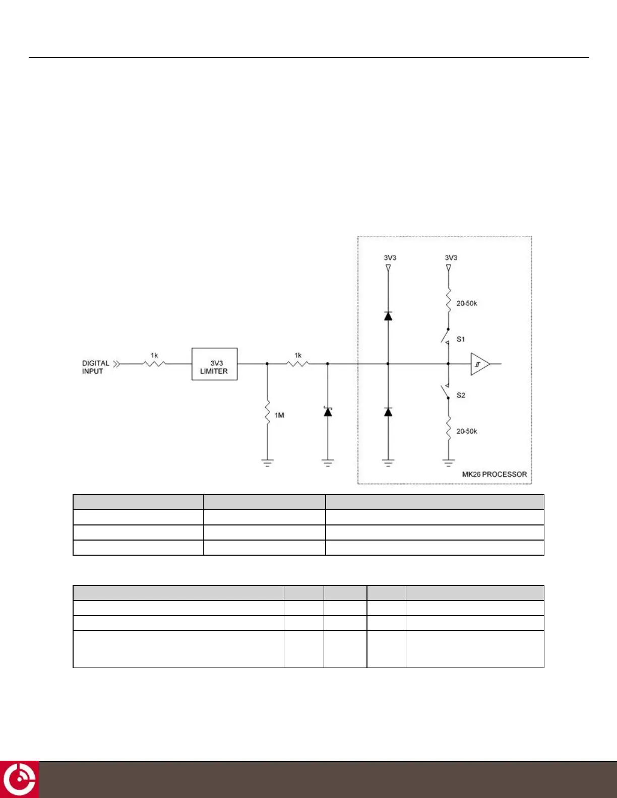
2.4.1.1 Digital Input
Figure 11 shows a schematic of the I/O when configured as a digital input.
Figure 11: Digital Input
Input Type S1 S2
With weak pull-down Open Open
With pull-down Open Closed
With pull-up Closed Open
The input specifications are provided in the table below.
Parameter Min. Typical Max. Units
Input low range -10 - 1.05 V
Input high range 1.95 - 150 V
Input current with weak pull-down
(weak 1 MΩ pull-down still in place);
V
in
= 3.0 V
- 4.5 - µA
T413, Version 0.04 BETA © ORBCOMM
®
Proprietary
20