ST 9100 - HARDWARE GUIDE
l Two (2) digital inputs and one 4-20 mA input or,
l Two (2) 0-5 V analog inputs and one 4-20mA input.
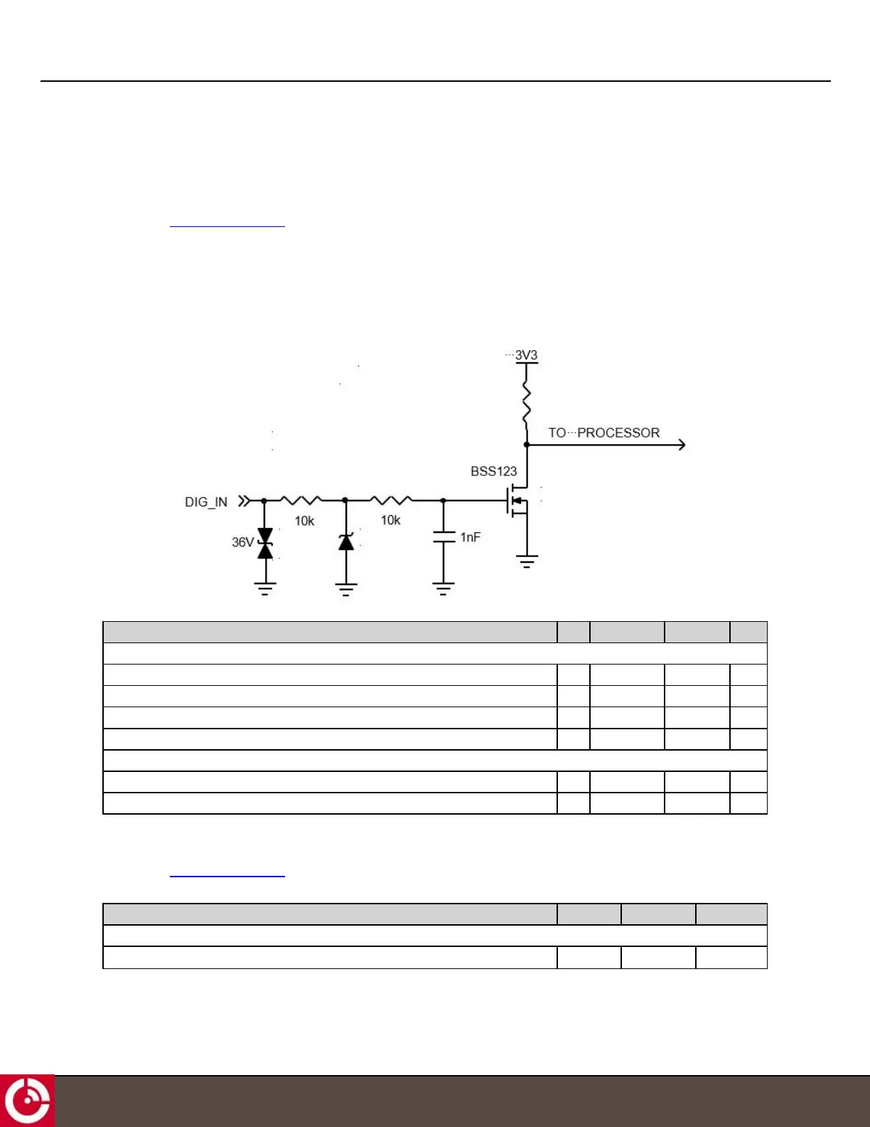
2.4.3.1 Input Only Ports
Four ports (PINs 2, 3, 16, and 24) can be configured as dedicated inputs. Each input is ESD protected by a 36 V
transient voltage suppressor that clamps the input transient at 58 V. A 15 V Zener ensures the FET maximum gate
voltage of 20 V is not exceeded.
Figure 15: Dedicated Inputs
Parameter Min. Max. Processor Units
Digital Input
Typical Input high voltage (Zener starts conducting at ±14.49 V) 1.6 14 0 V
Maximum input high voltage - 32 0 V
Input low voltage 0 1.4 3.3 V
Input frequency 1 10 - Hz
ESD
TVS breakdown voltage 40 44.2 - V
TVS clamp voltage - 58.1 - V
2.4.3.2 Analog Inputs (0-5 V)
Four ports (PINs 2, 3, 16, and 24) can be configured as dedicated 0-5 V analog inputs. 0-5 V applied to the ports is
converted to 0-3.3 V to be compatible with the ADC voltage range of the host processor.
Parameter Min. Max. Units
Analog Input
Input voltage range 0 5 V
T413, Version 0.04 BETA © ORBCOMM
®
Proprietary
24