ST 9100 - HARDWARE GUIDE
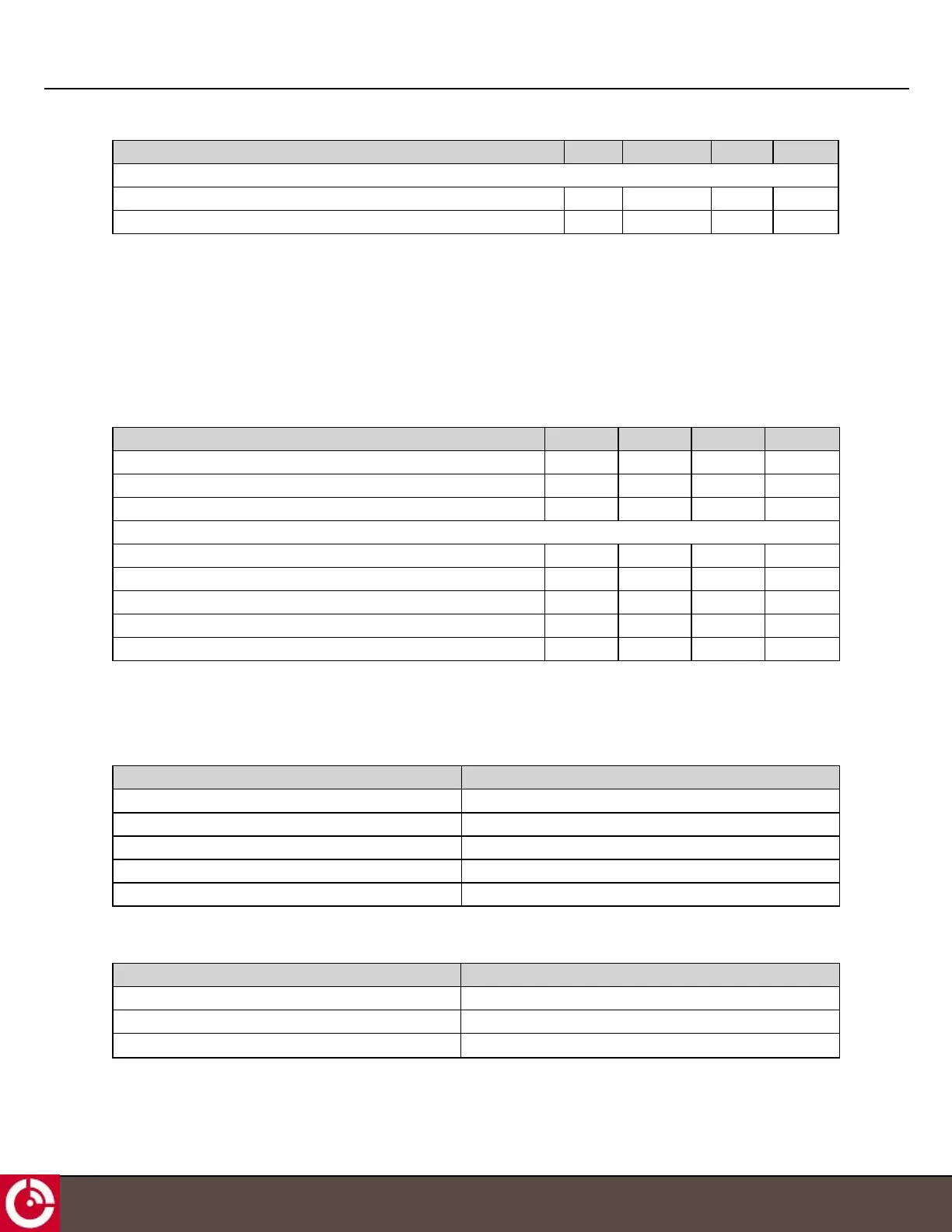
Parameter Min. Typical Max. Units
ESD Protection
Human Body Model - ±15 - kV
Contact Discharge Model - ±8 - kV
2.5.4 1-Wire
The 1-Wire interface allows connection to downstream 1-Wire devices connected on a bus, or to a single button
reader. Relative to any attached 1-Wire device, the transceiver behaves as the master. The 1-Wire driver supports 3 or
5 V devices on the bus.
At standard speed, the 1-Wire supports up to 39 devices over a 61-meter (200 feet) CAT5 cable. In overdrive, the
usable expected distance is reduced to ≤ 15 meters (≤ 50 feet) with a maximum node count of 9.
The electrical characteristics of the interface are:
Parameter Min. Typical Max. Units
1-Wire Input High Voltage 3 - - V
1-Wire Input Low Voltage - - 1 V
1-Wire Output Low Voltage (IOL - 8 mA sink current) - - 0.2 V
1-Wire ESD Protection Diode and Resistors
Avalanche Voltage 7.4 - 11.05 V
Trigger Voltage - 10 11 V
Holding Voltage (IOL - 8 mA sink current) 5.5 - - V
Holding Current 11 - - mA
Continuous Diode Current - - 80 mA
2.6 RF Specifications
2.6.1 Satellite (Standard) Antenna
Parameter Value
Maximum EIRP 7 dBW
Elevation Angle 20° to 90° degrees
Maximum transmit antenna gain 4.5 dBic
Rx Operating Frequency 1518-1559 MHz
Tx Operating Frequency 1626.5-1660.5 MHz, 1668-1675 MHz
2.6.2 Satellite (Low Elevation) Antenna
Parameter Value
Maximum EIRP 5 dBW
Elevation Angle -5° to 90° degrees
Maximum transmit antenna gain 2.5 dBic
T413, Version 0.04 BETA © ORBCOMM
®
Proprietary
27