ST 9100 - HARDWARE GUIDE
2.4.1.2.2 Switch to Ground
Parameter Min. Typical Max. Units
Sink current (do not exceed) - - 250 mA
Output voltage (sinking 250 mA)
I/O_1 to I/O_3
I/O_4
-
-
1.15
1.40
1.35
1.60
V
V
Absolute limits (high impedance) -10 - 150 V
Output bandwidth 100 - - Hz
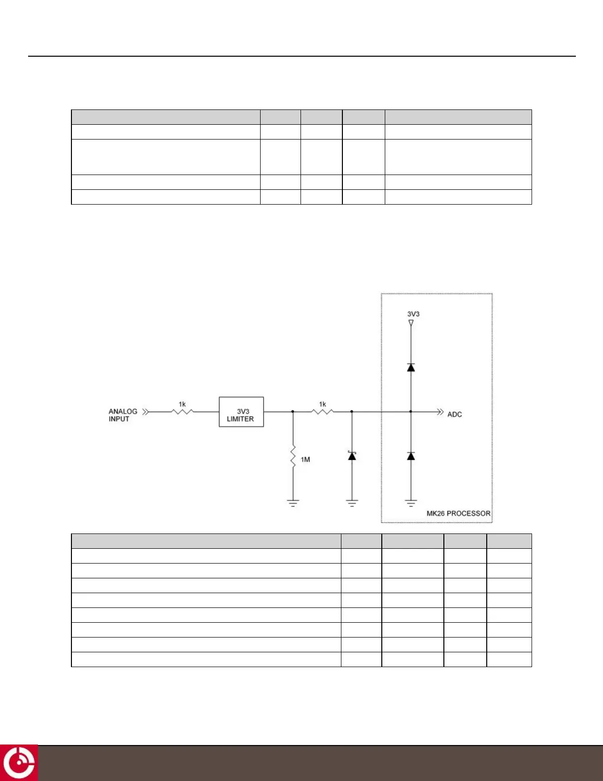
2.4.1.3 Analog Input
Figure 13 shows a schematic of the I/O when configured as an analog input.
Figure 13: Analog Input
Parameter Min. Typical Max. Units
Input impedance - 1 - MΩ
Minimum measurement voltage - 0 - V
Maximum measurement voltage 2.75 3.0 - V
Normal input range - - 3 V
Resolution (12 bits) - 0.7 - mV
Proportional measurement error - - 3 %
INL error - - 2 LSB
Absolute limits -10 - 150 V
T413, Version 0.04 BETA © ORBCOMM
®
Proprietary
22