ST 9100 - HARDWARE GUIDE
Parameter Min. Max. Units
Maximum input high voltage - 32 V
ESD
TVS breakdown voltage 40 44.2 V
TVS clamp voltage - 58.1 V
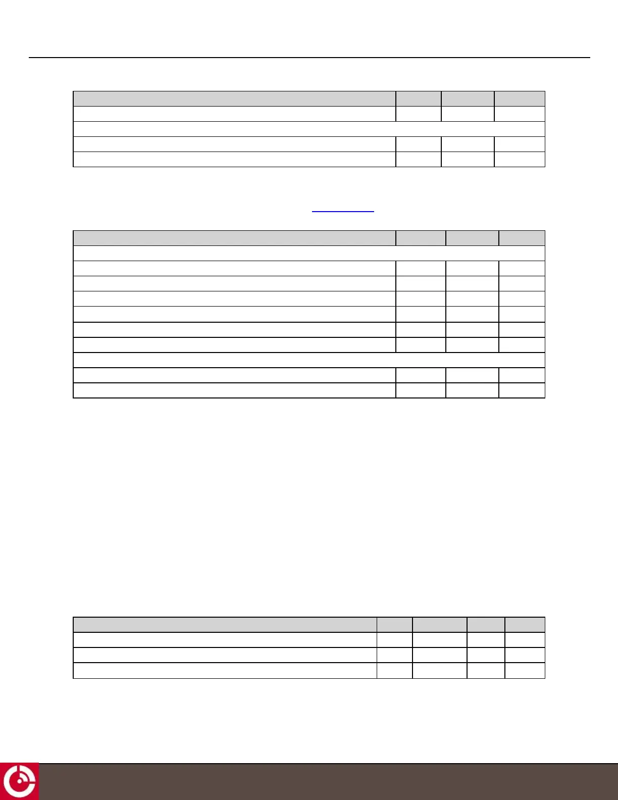
2.4.3.3 Inputs 4-20 mA
The ST9100 can monitor two 4-20 mA sensors. Two ports (PINs 16 and 24) can be configured as two dedicated 4-20
mA receivers.
Parameter Min. Max. Units
Current Loop
Operating current range 4 20 mA
Load voltage at 4 mA 0.396 0.404 V
Load voltage at 20 mA 1.98 2.02 V
Load resistance 99 101
Ω
Loop voltage (supplied by users externally) 10 32 V
Maximum input high voltage - 32 -
ESD
TVS breakdown voltage 40 44.2 V
TVS clamp voltage - 58.1 V
2.5 Serial Interfaces
Transceivers have the following interfaces:
l 2 x CAN Bus
l 1 x RS-485/J1708
l 2 x RS-232
l 1 x 1-Wire
2.5.1 CAN Bus
Note: CAN0 is available for BETA trials.
The transceiver provides two CAN Bus interfaces for sending and receiving frames.
The transceiver incorporates a controller area network interface with signaling rates up to 1 Mbps.
Note: You must provide a termination resistor externally to the transceiver.
Parameter Min. Typical Max. Units
Input Common Mode Voltage -7 - 12 V
Differential Input Threshold -6 - 6 V
Peak to Peak Output Common Mode Voltage - 1 - V
T413, Version 0.04 BETA © ORBCOMM
®
Proprietary
25