ST 9100 - HARDWARE GUIDE
Parameter Min. Typical Max. Units
Input source current with pull-up
(V
in
= 0.0 V)
- 75 - µA
Input sink current with pull-down
(V
in
= 3 to 150 V)
- 81 - µA
Input bandwidth 1 - - kHz
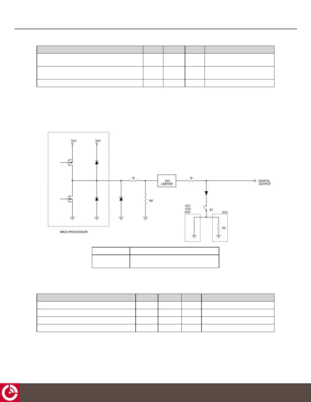
2.4.1.2 Digital Output
Figure 12 shows a schematic of the I/O when configured as a digital output.
Figure 12: Digital Output
Push-pull S1 = Open
Open drain S1 = Closed (Low Impedance)
S1 = Open (High Impedance)
2.4.1.2.1 Push-pull
In the push-pull configuration the output is driven directly from the microprocessor.
Parameter Min. Typical Max. Units
Output high voltage - open circuit 2.65 3.0 3.15 V
Output high voltage (sourcing 25 µA) 2.50 - - V
Output low voltage (sinking 25 µA) - - 0.05 V
Output bandwidth 100 - - Hz
T413, Version 0.04 BETA © ORBCOMM
®
Proprietary
21