ST 9100 - HARDWARE GUIDE
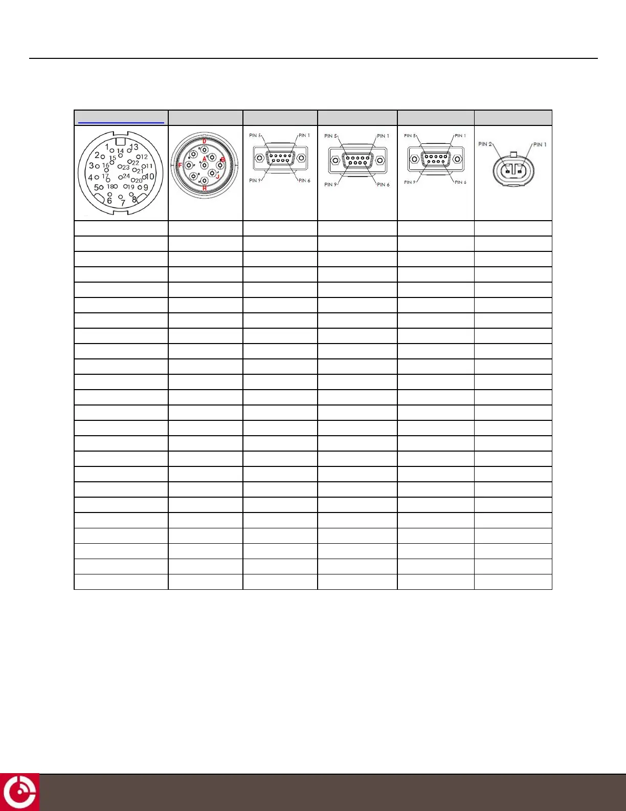
Table 7: Development Cable Connectors
Transceiver Connector End A End B End C End D End E
PIN 9 - 1Wire Com
PIN 10 - RS232 TX PIN 2
PIN 21 - RS232 RX PIN 3
PIN 22 - AUX RS232 TX PIN 2
PIN 13 - CAN 1 Low PIND
PIN 14 - CAN 0 Low PIN J
PIN 1 - RS485 A PIN 1
PIN 24 - Dig IN 2
PIN 16 - Dig IN1
PIN 4 - I/O_4
PIN 5 - I/O_2
PIN 6 _ Ground PIN A and PIN E PIN 5 PIN5 PIN 5 PIN 2
PIN 7 - VEXT PINB PIN 1
PIN 8 - Out 6
PIN 18 - I/O_1
PIN 17 - I/O_3
PIN 3 - Dig IN 3
PIN 15 - RS485 B PIN 2
PIN 23 - CAN 0 High PIN H
PIN 12 - CAN 1 High PINC
PIN 11 - AUX RS232 RX PIN 3
PIN 20 - 1Wire Data
PIN 19 - Out 5
PIN 2 - Dig IN 4
T413, Version 0.04 BETA © ORBCOMM
®
Proprietary
40