Installation
900-0009-01-00 Rev C 11
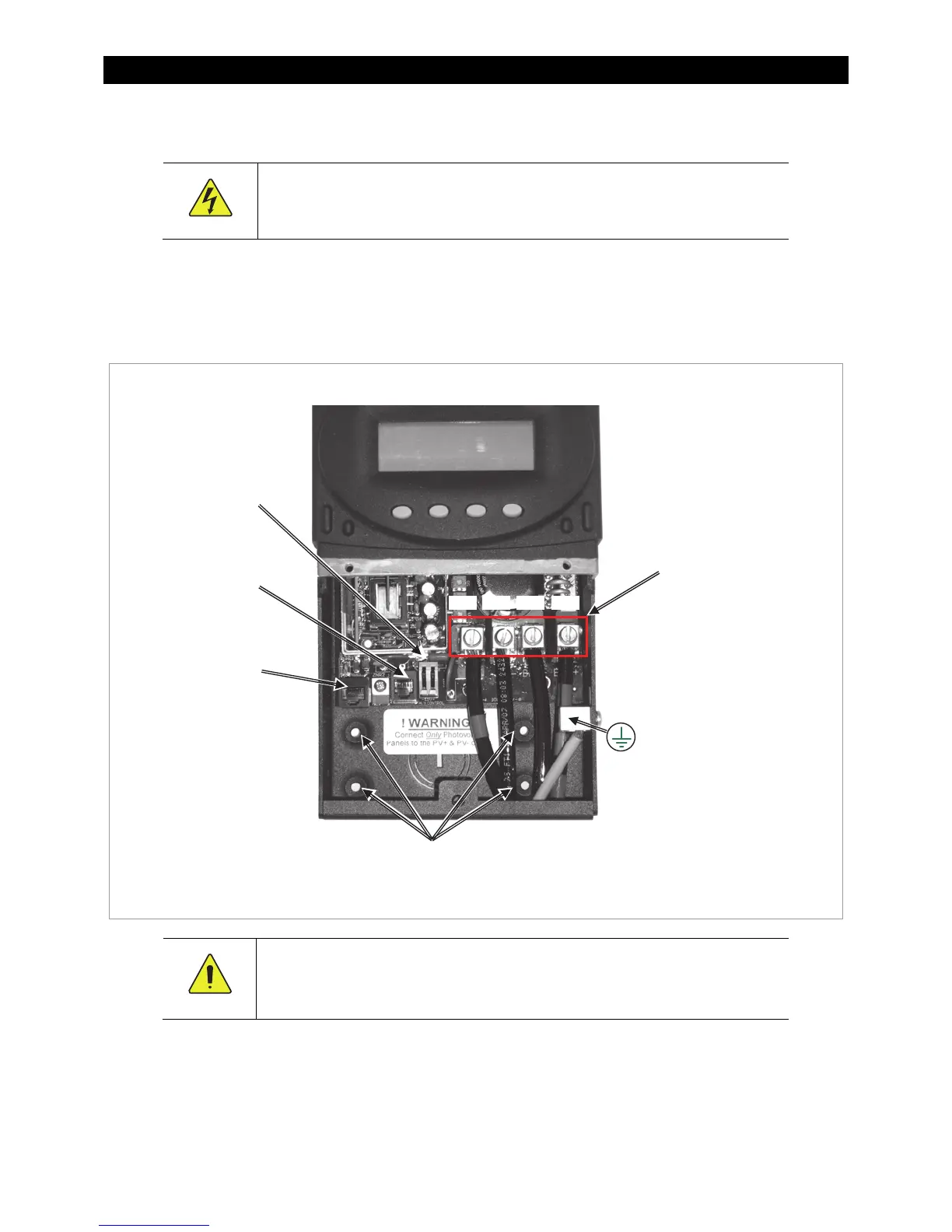
Wiring Compartment
WARNING: Shock Hazard
Make sure all DC circuit breakers are OFF (open) BEFORE making any wiring
connections. Use a DVM to check for voltage on all wires.
The PV (-) and BAT (-) terminals are connected internally. Only one negative wire may be needed to
connect to the (-) wire lugs if the PV - and BAT- conductors are bonded at the negative bus bar.
See Figure 6, Figure 7, and Figure 8 for sample wiring diagrams.
Figure 5 Wiring Compartment
CAUTION: Equipment Damage
Each FLEXmax requires its own PV array. DO NOT PARALLEL FLEXmax PV+ and PV-
TERMINALS ON THE SAME ARRAY!
An optional battery Remote Temperature Sensor (RTS) is recommended for accurate battery charging.
Only one RTS is needed for multiple OutBack inverter/chargers and charge controller units when the system
includes an OutBack HUB and a system display.
When one RTS is used, it must be connected to the component plugged into the Port 1 of the HUB.
Chassis/Equipment
Ground Lug
Use up to 35 mm
2
(2 AWG) wire
Torque to 4 Nm
(35 in-lb)
MATE/HUB
RJ45 port
Battery Remote
Temp Sensor (RTS)
RJ11 port
Auxiliary output
terminals
Wire terminals
Screw holes for mounting the
charge controller
PV+ PV– BAT– BAT+