L-737-3-E
27
●
Terminal identification and description
Item Label Description Remarks
Signal
A1(+)
Analog output 1 (4 to 20mA)
1. Max. load resistance is 600Ω
for analog output 1 and 2.
2. Pulse output (voltage
pulse) transmission length is
Max. 10m (at 10kHz)
Max. 100m (at 1kHz)
Max. 1km (at 100Hz)
finished O.D: 0.75sq
3. These input and output signals
are invalid for FOUNDATION
fieldbus, PROFIBUS PA and
Modbus communications.
A1(-)
A2(+)
Analog output 2 (4 to 20mA)
A2(-)
P1(+)
Pulse output 1
(voltage/open drain output)
P1(-)
P2(+)
Pulse output 2
(voltage/open drain output)
P2(-)
S.I.(+)
Status input (drain input)
S.I.(-)
S.O.(+)
Status output (open drain output)
S.O.(-)
I/O(+)
Expanded in/out
(Modbus communication, etc.)
Modbus communication:Max.trans-
mission length1200m at 0.75sq
FOUNDATION fieldbus or
PROFIBUS PA communication:
Max. transmission length 1900m at
0.8sq
I/O(-)
Power
L(+) Power (with DC power: +)
GND Earth ground
N(-) Power (with DC power: –)
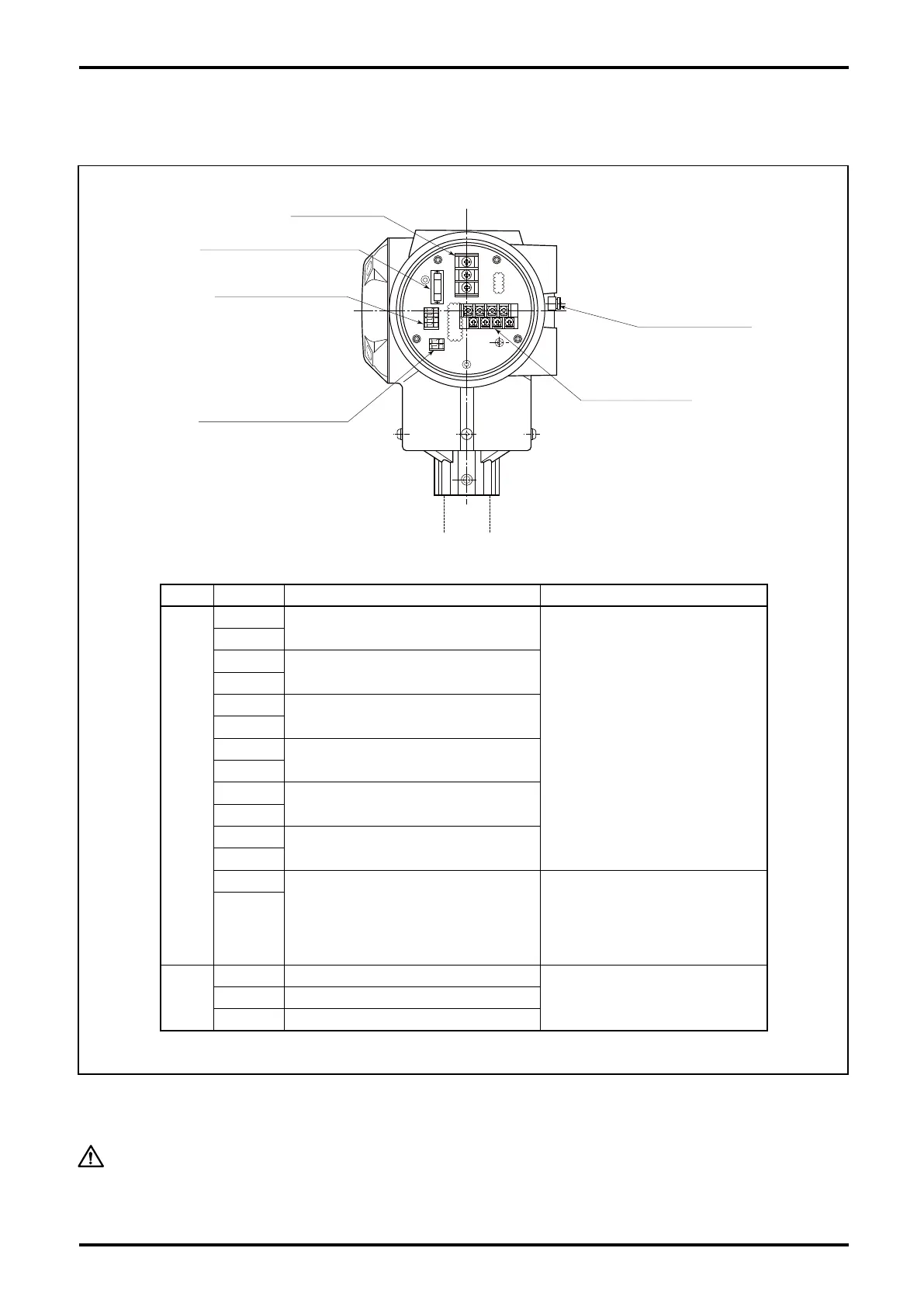
Fig.6.9
Status in/out terminals
Analog and pulse
output terminals
Power terminals
Replaceable fuse 250V, 2A
Remote output terminals
Ext. GND terminals
6.11 Wiring Diagram
6.11.1 Transmitter power and output signal wiring
Conduct earth grounding work at external ground terminal or "GND" on the power terminal block (Grade
D grounding work).
CAUTION:
Incase supplying electric power to this flowmeter, do not fail to connect a
protective fuse of rated voltage 2A max.

 Loading...


