L-737-3-E
22
6. WIRING INSTRUCTIONS
6.1 Terminal Box Cover Removal
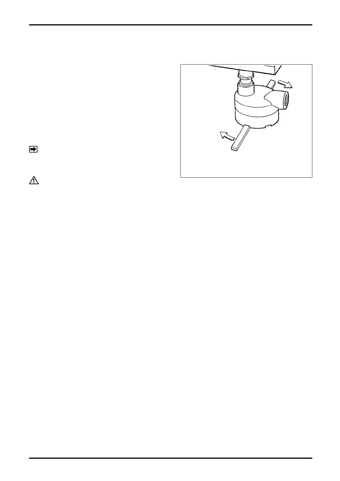
Cable entrance from the transmitter is found on the
bottom of sensor unit. Remove its cover and make
wiring connections at respective terminals.
(1) Using a flat tool, loosen the terminal box cover by
slowly turning it clockwise and then hand rotate it
further until it comes off.
(2) Removing the cover provides access to the
terminal block.
(3) Cover reinstallation is the reverse of the removal
procedure in step (1).
CAUTION:
By changing the physical orientation of terminal
box, the internal wiring could be broken if it
is pulled too strongly. If you desire a change,
consult OVAL.
Fig. 6.1
Terminal Box
Terminal Cover
A Flat Tool (that will not
scratch the finish)
Turn
For the explanation of connecting terminals
i n s i d e t h e te r m i n a l b o x , r e f e r t o 7.
REMOTELY MOUNTED TRANSMITTER
AND SENSOR UNIT WIRING.
NOTE:
6.2 Wiring Connections
6.2.1 Cable lead-in
For explosionproof models, use the cable gland supplied in the shipment.
For the specifications of the cable gland, refer to 10.5 About Cable Gland.