L-737-3-E
12
5. INSTALLATION
5.1 Considerations at Installation
(1) Select a location easy to access for inspection and maintenance.
(2) Avoid locations subject to severe temperature variation and vibration.
(3) Avoid direct exposure to the sun. (Provide a sunshade or visor if necessarry.)
(4) Avoid locations where there is a risk of immersion in water.
(5) Select a location free from an atmosphere of corrosive gases.
(6) Location should be free from dust and mist.
(7) Keep a distance of at least one meter from sources of electromagnetic induction, such as large
transformers and motors. Install sufficiently away from motors, pumps, or other sources of high vibration.
(8) To ensure consistent and accurate measurement, adhere to the instructions for tubing clamps on page 16.
(9) To ensure accurate and consistent measurement, use the Coriolis flowmeter in a location where piping
vibration is kept below 0.3G.
(10) Instal the control valve downstream of the flowmeter.
Where cavitation may possibly occur, install the valve at least five meters away from your meter.
5.2 Physical Orientation
Physical orientation does not affect the performance of this unit. It can be installed either in a horizontal or
vertical run. However, with metered fluids that tend to produce bubbles and/or sediments, or where process
fluid removal or purging is conducted after measurement, install the unit in a vertical run.
5.3 Piping Instructions
5.3.1 Standard Piping Conditions
(1) A Coriolis mass flowmeter is unaffected by the
flow pattern of process fluid.
T h e r e fo r e, i t do e s n o t r e q u i r e a ny f l o w
straightener. However, connection with a
deformed pipe requires use of a concentric
reducer or tapered pipe.
(2) Locate the meter sufficiently away from known
sources of vibration and pulsation.
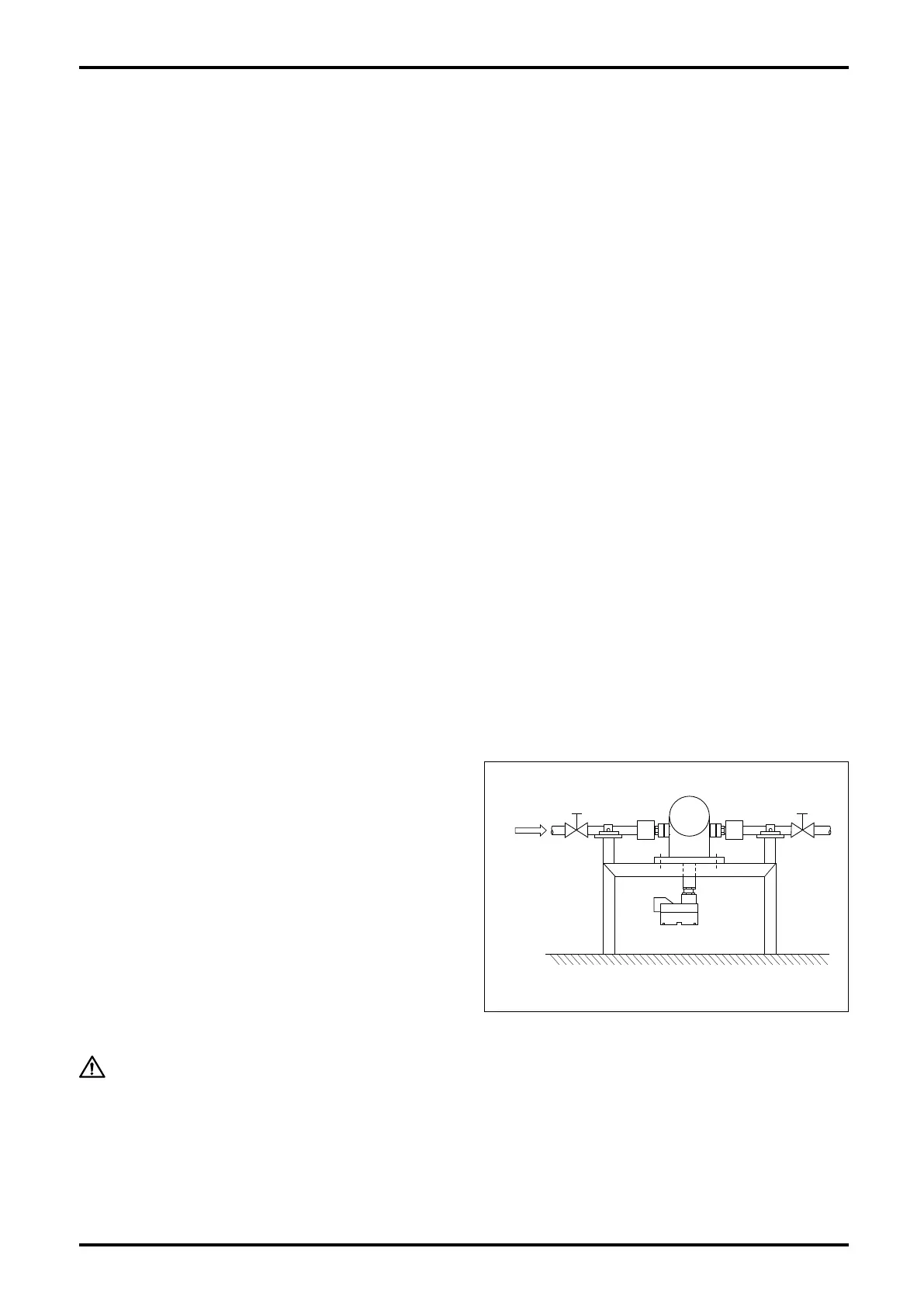
(3) For zeroing, provide a valve that can stop the
flow completely downstream of the meter. We
recommend to provide another valve upstream
of the meter for servicing.
(4) Avoid piping stress concentration on the sensor.
CAUTION:
Although this meter is designed for installation on a mounting base, piping
clamps must be provided both upstream and downstream of the meter.
Fig. 5.1 Standard Piping Conditions
Flow
Direction
Valve
Valve

 Loading...


