L-737-3-E
28
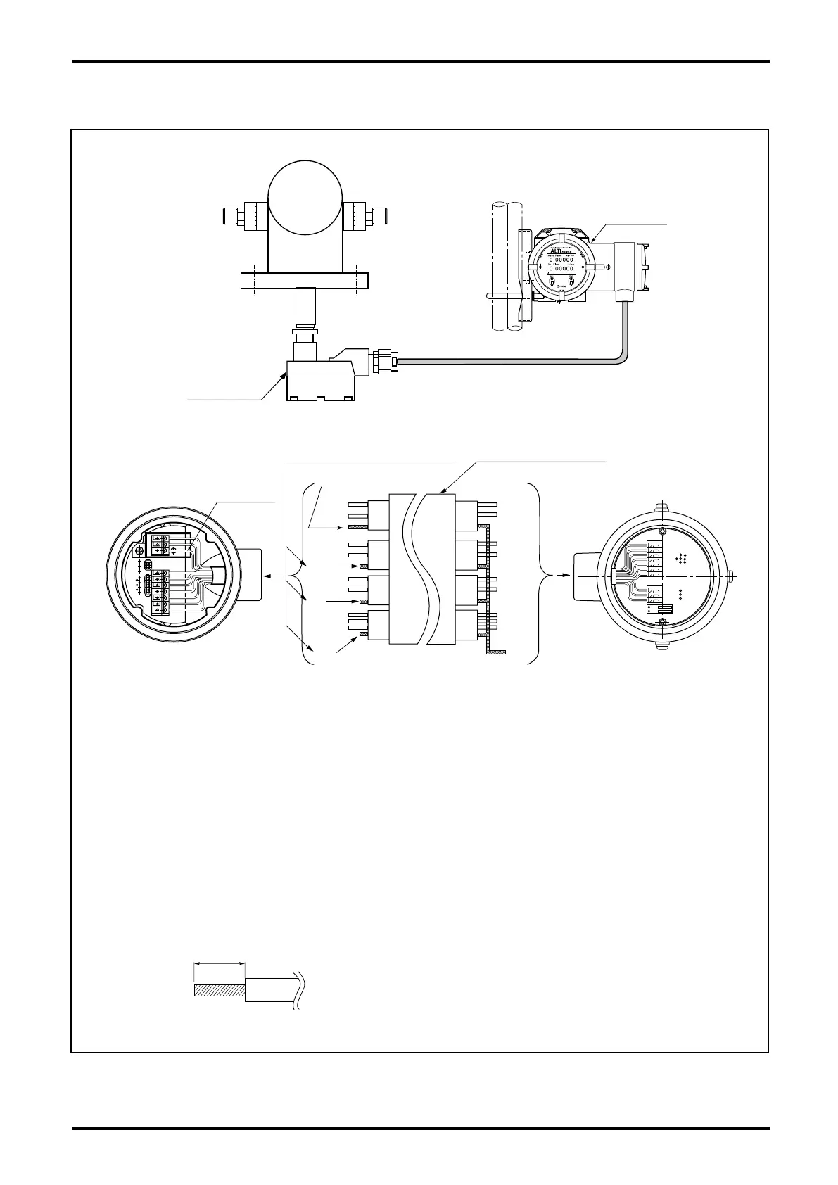
Sensor unit
Terminal Box
T
ransmitter
7. REMOTELY MOUNTED TRANSMITTER AND SENSOR UNIT WIRING
Fig.7.1
Cut off shield wires here except for the
shield wire over BRN and RED lines.
Interconnect
cable (Max. 200m)
Transmitter terminal box
Sensor terminal box
Shield
(Protected by black tube)
Shield
(Protected by black tube)
cut
cut
cut
Brown
Red
Green
White
Blue
Grey
Purple
Yellow
Orange
Brown
Red
Green
White
Blue
Grey
Purple
Yellow
Orange
Shield wires:Black
茶
赤
黒
橙
黄
緑
青
紫
灰
白
NOTE 1. Make sure to use dedicated interconnect cable.
2. Shield wire preparation
(1) Transmitter end :
As shown in the above figure, bundle shield wires colored in brown/red, green/
white, blue/grey, purple/yellow/orange, twist them, and cover the wires with a black
tube. Then connect only one wire to the terminal box (black) taking care to avoid
potential contact with the housing or conductive parts.
(2) Sensor en
d:
As shown in the figure, cover the brown/red shield wire with a black tube and
connect it to the terminal box taking care to avoid potential contact with the housing
or conductive parts. Clip all shield wires except brown/red as shown in the above
figure.
3. Recommended cable end treatment:
Use of a stick type crimp terminal is not necessary.