L-737-3-E
84
10.5.3 Insulation performance
Part of transmitter (PA0K) subject to insulation:
IS circuit terminals (separate detector board: TB20, TB21) - Enclosure
Withstand voltage condition: 500VAC, leak current: 3 to 5mA
Due to the built-in noise eliminator between the transmitter power source terminals (TB1’s L and N) and
output terminals (TB2, TB3 and TB4), and the enclosure respectively, complete insulation is not provided.
In case withstand voltage test is conducted across these parts, please conduct under the conditions
below.
Withstand voltage condition: AC200V or DC250V, leak current: 3 to 5mA
10.5.4 Earthing terminal
1. Use GND of power source terminal block or any of external grounding terminals.
2. Use wires of cross section area of 4mm
2
min. (AWG11 min.) for grounding.
3. Coating color of the grounding wires shall be green or stripe of green and yellow.
4. Class D grounding (100 ohm or less) is recommended.
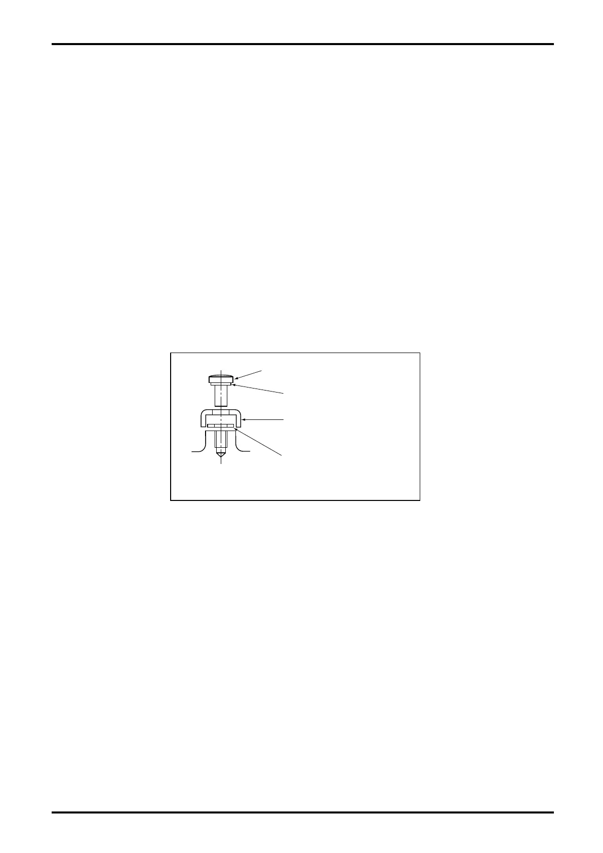
5. In case external wirings are used, make sure that the grounding wire is connected with the earth
terminal cover and plain washer in the sketch below.
10.5.5 About dedicated cable (for only separate type)
1. In case of separate type, a dedicated cable is used for connection between the sensor and
transmitter. Use of other cables are not allowed from the point of explosionproof.
2. Make sure to array the dedicated cable between the sensor and transmitter so that any current and
voltage, which attributable to electromagnetic induction or electrostatic induction and could impair
the intrinsic safety performance of the IS circuit, is never induced.
Cross recess pan head screw
Fig.10.2