L-737-3-E
15
5.5.2 Connection Procedure
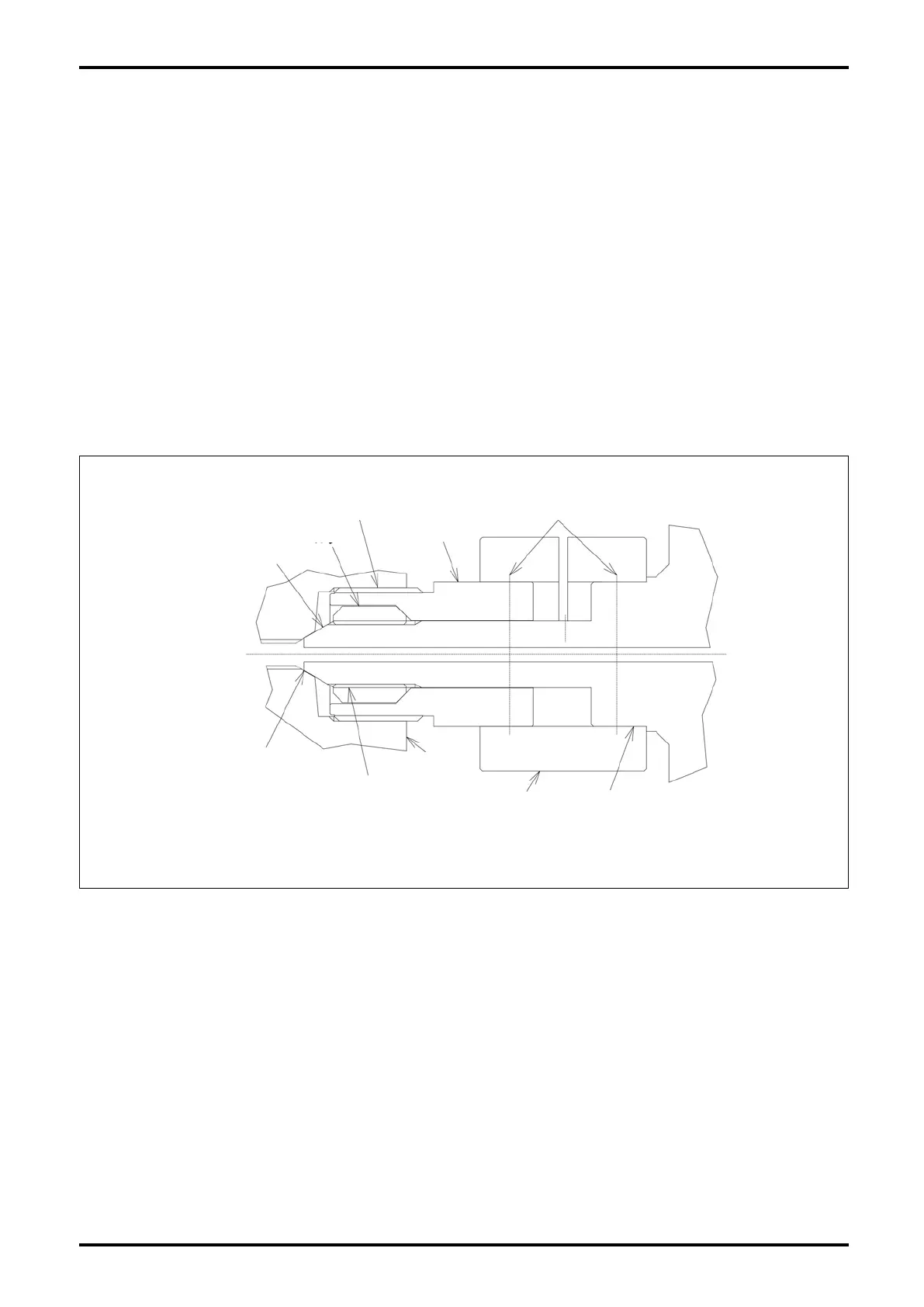
(See Figs. 5.4 and 5.6.)
(1) Loosen two M6 hex socket head bolts attached to the connector clamp.
(2) Slide the gland nut onto the male connector and insert the collar as shown in Fig. 5.6 (reverse thread).
Collar position is correct if it has been screwed in to the point where one or two threads are visible at the
end of male connector. Normally it is installed in place at our factory.
(3) Ensure that both the cone of the male connector and the customer furnished female connector are clean.
(4) Insert the male connector into the female connector and finger tighten the gland nut. Ensure that the male
connector and female connector are aligned in their axis at this time.
(5) Tighten the gland nut to a tightening torque not exceeding 279kgf・cm [27.4N・m]. When tightening,
hold the female connector using a wrench.
(6) Insert the connector clamp until it comes to the stepped part of the sleeve.
(7) Tighten two M6 hex socket head bolts attached to the connector clamp to secure the gland nut-to-sleeve
firmly.
Fig. 5.6 Detail Drawing of Connectors (high pressure cone & thread connection, 9/16" dia. 562C)
Male Connector
Collar
1・1/8-12UNF
Gland Nut
M6 Socket Head Bolt (2 Places)
Metal Seal
9/16-18 UNF LH
Female
Connector
Sleeve
Connector
Clamp
Flowmeter
Body




 To Next Page