L-737-3-E
9
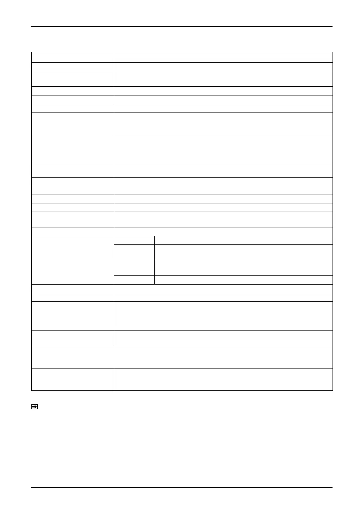
3.2 Transmitter general specifications
Item Description
Model PA0K
Power supply
85 to 264VAC 50/60Hz or 20 to 30VDC
(Safety rated 100 to 240VAC 50/60Hz)
Power consumption Max. 15W
Ambient temperature - 40 to +55℃ ( ※ 1)
Transmission length (separate type)
Max. 200m (Dedicated cable used) ( ※ 2)
Applicable EU directive
EMC Diective :2014/30/EU
ATEX Diective:94/9/EC
LVD Diective :2014/35/EU
Applicable EN standards
EMC :EN61326-1:2013 ClassA
ATEX:EN60079-0:2012 EN60079-1:2007 EN60079-11:2012
IECEx:IEC60079-0:2011 IEC60079-1:2007-04 IEC60079-11:2011
LVD :EN61010-1:2010
Explosionproof configuration
ATEX, IECEx, KCs, CSA, GOST, NEPSI
(See the topic under 10.4 Explosionproof specification)
Maritime certification DNV GL (Refer to section 12)
Dusttight, waterproof configuration IP66 / 67
Transmitter configuration Integral or separately mounted
Finish Sensor: Munsell 10B8/4, Covers (front and rear): 2.5PB4/10
Display
LCD display provided (128 × 64 dots), backlit (white, orange)
Infrared light sensors: 2, LED: 2 (green, red)
Weight Integrally mounted model 3.6kg approx., Separately mounted model 5.0kg approx.
Communication interface
※ Optional except for HART
HART (Standard)
HART protocol version 7, Bell202 ( ※ 3)
Modbus
RS-485 Modbus protocol, Baudrate : 9600bps, 19200bps, 38400bps
RTU or ASCII, Response time : 25 to 50 ms
FOUNDATION
fieldbus
AI block × 4, IT block × 2, with Link Master function
PROFIBUS PA AI block × 4, TOT block × 2
Damping (default)
Flow rate 0.8sec, density 4sec, temperature 2.5sec.
Low flow cutoff (default)
Under 0.6% of max. service flow rate
Pulse output ( ※ 5)
Open drain output (equivalent to open collector output ) [Min. 10V to Max. 30V, 50mADC, ON
resiatance 0.6Ω or less] or
Voltage pulse (Low level: 1.5V max., High level: 13V min. Output impedance: 2.2k Ω )
Setting range: 0.1 to 10000Hz (Max. output 11000Hz)
Analog output ( ※ 5)
4 to 20mADC (max. load 600Ω)
Select two outputs from instant flowrate (mass or volume) temperature, and density.
Status output ( ※ 5)
Open drain output (equivalent to open collector output ) [Max. 30V, 50mADC, ON resiatance
0.6Ω or less]
Select one output from error ( ※ 4), flow direction, or high/low alarm (default is error)
Status input ( ※ 5)
Contact-closure input (Form "a" contact) Short: 200 Ω max., Open: 100k Ω min.
Select one output from remote zero, total reset, 0% signal lock, or function off (default is
function off).
※1: Below -20℃, the display loses its visibility due to weakened contrast. Both the display and infrared sensor
may exhibit slow responses below -20℃.
※2: If signal transmission length exceeds the maximum transmission length, consult OVAL.
※3: Of the two analog output systems,only analog output 1 is available for HART communication.
※4: Of error outputs, "zero is in progress" status output can also be set up.
※5: When FOUNDATION fieldbus, PROFIBUS PA is selected as the communication interface, all input and
output signals will be turned off.
※: Denoising parts are embedded in the lines between power source, output, communication, and the chassis.
Lower the applied voltage to the following levels in order to conduct insulation test or withstand voltage test
on these lines.
AC: 200V, DC: 250V
NOTES