TEST AND MEASUREMENT
MCUK990801C8 Section 6 Issue 1
Service Manual – 45 – Revision 0
17. Repeat steps 6 to 15 for GSM1800 on the channels listed below.
6.6 I and Q Values
NOTE: By observing the image leakage and adjusting the relative gain between I and Q channels, phase error and
modulation spectrum can be improved. With the I, Qch adjustment procedures the transmitter must be set to
Power Level 5 (this presents the worst case of non-linearity) so care must be taken that the spectrum analyser
used can accept a signal input of 33dBm. If not, an appropriate attenuator must be used.
I, Qch Gain
IMPORTANT: I, Qch offset calibration should be done before this calibration.
Spectrum Analyser Setup.
centre frequency = 902.4MHz
RBW = 10kHz
VBW = 10kHz
Span = 1MHz
Sweep time = 2sec
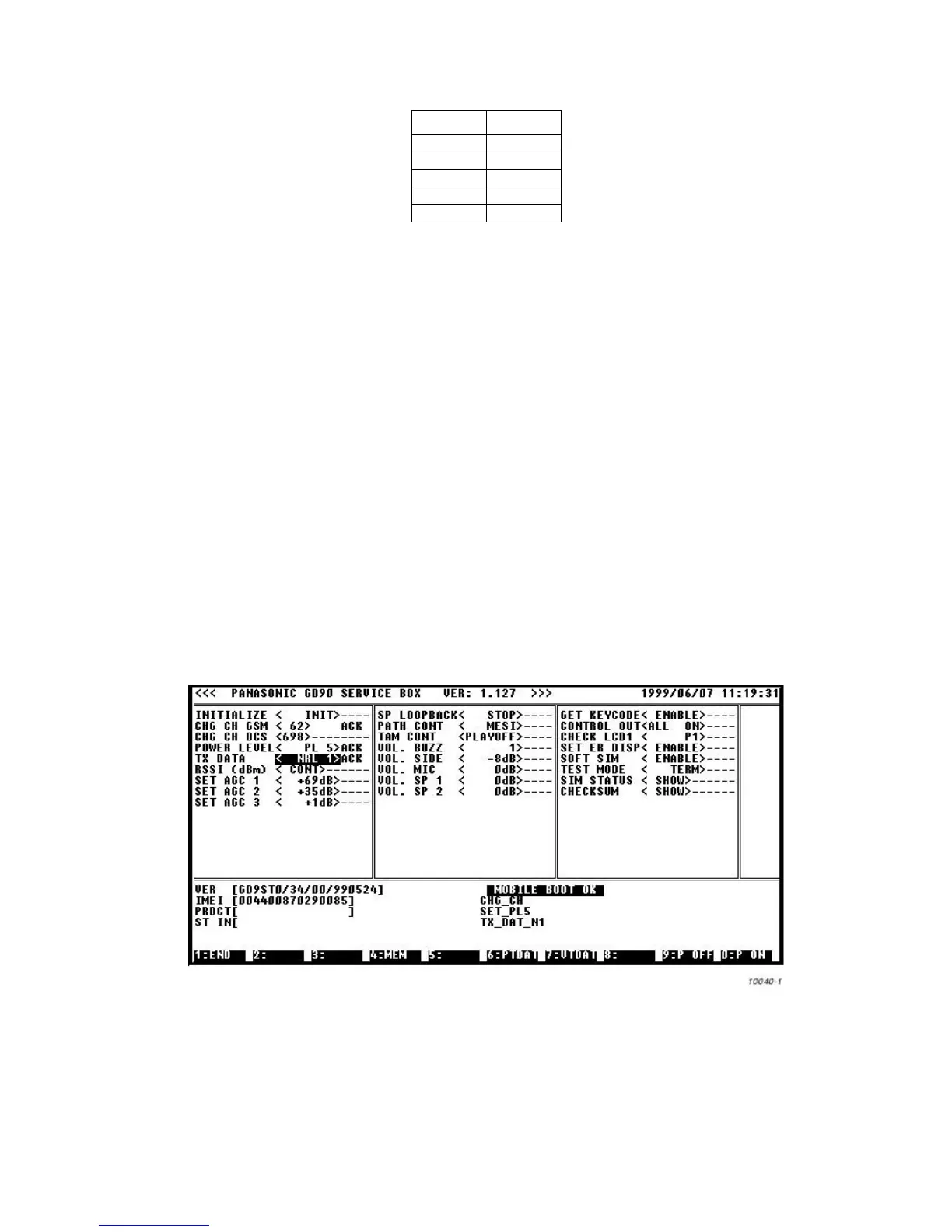
1. On the Channel box, highlight CHANGE CH GSM.
a. Press the left-right arrow keys until channel number ‘62’ is visible in the window. Press ENTER to select.
b. Press the down-arrow key until the POWER LEVEL field is highlighted. Press the left-right arrow keys until PL5 is visible
in the window. Press ENTER to select.
c. Press the down arrow until the TX DATA field is highlighted. Press the left-right arrow keys until NRL1 is visible in the
window. Press ENTER to select.
Figure 6.24: Image leak ratio
2. Using the spectrum analyser measure the image leak ratio. Image leak ratio is the measured ratio of peak power and the
power at 135 kHz below peak frequency.
Example:
peak power (902.468 Mhz) = 33 dBm
power at 135 kHz below peak power = -9 dBm
image leak ratio = 33 dBm - (-9 dBm) = 42 dBm
Channel GSM 1800
Bch 520
Lch 630
Mch 700
Hch 810
Tch 870