Installing the Drive 3-3
650 Series AC Drive
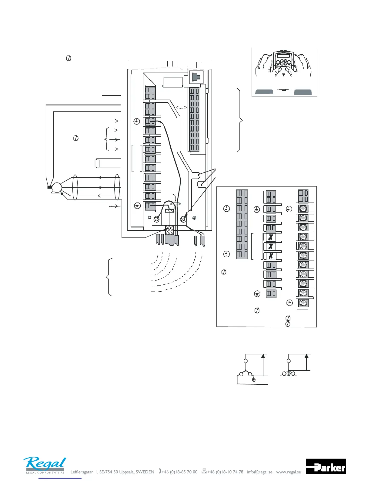
Connection Diagram
10
9
8
7
6
5
4
3
2
1
M2/V
M3/W
L1
TH1A
TH1B
L2/N
RL1A
RL1B
13
12
11
M1/U
Motor Protective Earth/Ground
(future option)
Control Cables
User Relay Cable
Supply Cable
Motor Cable
Ther mi stor Cabl e
Dynamic Brake Cab le
screen and
earth wire
connections
only
shown for
clarit y
M
external brake resistor
Motor Thermistor
(400V unit only)
Volt -
free
Contacts
screen
Supply Protective Earth/Gr ound
3
380-46 0V ac
DIN4/ DOUT 2
DIN3/ DOUT 1
DIN1
+24V
AOUT1
+10V REF
AIN2
AIN1 *
0V
DIN2
Connect the 0V/COMMON to protective earth/ground.
connect the 0V/COMMON signals and join to
In a system com prising more than one controller,
prot ect ive e ar t h/ gr o un d a t one p oint on l y.
This is mandatory to meet the EMC specification stated.
*
two
separate
use
p rot ect i ve
earth
wires
Motor Screen Earth/Ground
fix cable
tie here
press here and slide down
To remove the Terminal Cover
Wire Retainers
Screen Earth/Ground
DBR
L3
DC+
Volt-free relay terminals can
be us ed as eit he r `l i ve ’ or S ELV.
1 : RL1A, RL1B
Motor thermistor connections are
regarded as a `live circuit’ and
mu st not be c on n ecte d to S EL V ci rc ui ts .
2 :TH1A, TH1B
See Note 1
See
Note 2
RS232
port
P3
Refer to Chapter 12: "Applications"
for specific control wiring for each
Application
Wiring Instructions
IMPORTANT:
Note that the 650 unit must be permanently earthed using two independent protective earth/ground incoming supply conductors.
1 Remove the terminal cover from the drive.
2 Loosen the motor cable screen clamp.
3 Connect t he power supply cable, motor cable and control cables (if required).
4 Fasten the motor cable in place with the motor cable screen clamp.
Frames 2 & 3 only : Secure control cables under the wire retainers.
5 Connect t he thermistor and user-relay if required.
Frames 2 & 3 only: connect the dynamic brake if required (3 phase units only).
6 Use a cable t ie and secure all the control cables and user - relay cables (if fitted)
7 Connect t he ancillary equipment as shown, for example, an external brake resistor.
8 Re-fit the terminal cover.
Secure any control cable screen connections under the right hand screw.
as close to the control terminals as possible.
TN IT
Non-earth referenced
supply
Earth referenced
supply
The dri ve is suitable for use with earth
fitted with an internal ac supply EMC filter.
refer enced supplies (TN) and non -ea rth
Frame 2
3 380-460V ac
(see Power Terminal Variations
inset for other frame sizes)
referenced supplies (IT) when
M2/V
M3/W
L1
TH1A
TH1B
L2/N
M1/U
DBR
L3
DC+
1
220-24 0V ac
Frame 2
3
220-240V ac
Frame 3
M1/U
M2/V
M3/W
L1
TH1A
TH1B
L2/N
1
220-240V ac
Frame 1
Power Terminal
Variations
3
380-460V ac
L3
M2/V
M3/W
L1
L2
M1/U
DC+
DBR
DC
TH1A
TH1B
-
* If AIN1 is not used, connect to 0V

 Loading...


