3-4 Installing the Drive
650 Series AC Drive
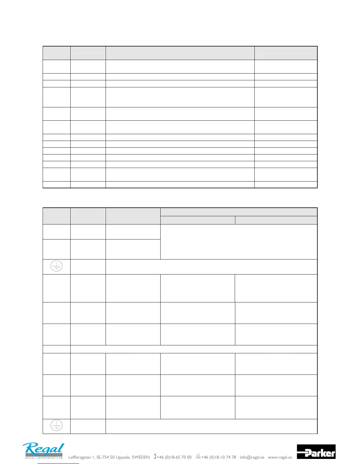
Control Wiring Connections
Terminal
(SELV)
Description Application 1 Default Function
(for other Applications refer to Chapter 12: “Applications”)
Range
P3 P3 RS232 port for use with remote-mounted RS232 keypad or
programming PC
-
RL1A User Relay Volt-free contact 0-250Vac/24Vdc 4A
RL1B User Relay Volt-free contact 0-250Vac/24Vdc 4A
10 DIN4/
DOUT2
Configurable digital input/output
Not Stop (input):
0V = No latching of Run (DIN1), 24V = Run latched
0-24V source open
collector 50mA
maximum
9 DIN3/
DOUT1
Jog – configurable digital input:
0V = Stop, 24V = Jog
0-24V
8 DIN2 Direction – configurable digital input:
0V = Forward, 24V = Reverse
0-24V
7 DIN1 Run – configurable digital input: 0V = Stop, 24V = Run 0-24V
6 +24V 24V – 24V supply for digital I/O 50mA maximum
5 AOUT1 Ramp Output – configurable analog output (10mA loading) 0-10V
4 10VREF 10V - 10V reference (10mA maximum loading) 10V
3 AIN2 Feedback – analog input 2 0-10V, 4-20mA
2 AIN1 Setpoint – analog input 1.
If AIN 1 is not used, connect to 0V.
0-10V
1 0V 0V - 0V reference for analog/digital I/O 0V
Power Wiring Connections
Terminal Description Function Range
200V 1-Phase 200V/400V 3-Phase
TH1A Thermistor Connection to motor
thermistor
TH1B Thermistor Connection to motor
thermistor
It is good practice to protect motors by fitting temperature
sensitive resistors. A typical resistance (up to a reference
temperature of 125°C) is 200Ω, rising rapidly to 2000Ω above
this temperature. Connect devices in series between TH1A and
TH1B. Link the terminals if temperature sensors are not used.
Reference
Terminal
Supply protective earth (PE). This terminal must be connected to a protective (earth)
ground for permanent earthing.
L1 Power Input Single and three
phase live
connection
220/240V ac ±10% rms with
respect to L2/N. 50-60Hz
(IT/TN)
220/240V or 380/460V ac
±10% rms with respect to L2, L3
phase-to-phase. 50-60Hz
(IT/TN)
L2/N
L2
Power Input Single phase neutral
(or L2 three phase
live connection)
220/240V ac ±10% with
respect to L1. 50-60Hz
(IT/TN)
220/240V or 380/460V ac
±10% with respect to L1, L3.
50-60Hz (IT/TN)
L3 Power Input Three phase live
connection
Not applicable 220/240V or 380/460V ac
±10% with respect to L1, L2.
50-60Hz (IT/TN)
DC- No user connection
DC+ Dynamic
Brake
Connection to
external brake
resistor
Not applicable Frame 2 (high volt only) & 3.
See “Internal Dynamic Brake
Switch” table
DBR Dynamic
Brake
Connection to
external brake
resistor
Not applicable Frame 2 (high volt only) & 3.
See “Internal Dynamic Brake
Switch” table
M1/U
M2/V
M3/W
Motor
Outputs
Connection for
motor
Motor rated at:
0 to 220/240V ac
0 to 240Hz
Motor rated at:
0 to 220/240V or 380/460V ac
0 to 240Hz
Reference
Terminal
Supply protective earth (PE). This terminal must be connected to a protective (earth)
ground for permanent earthing.

 Loading...


