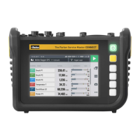
CAN + AUX model version
2 3 41
Fig.4 Connections, CAN + AUX model version
Pos. Designation Description
1 CAN Bus To connect Parker CAN bus sensors with auto-
matic sensor detection
2 AUX connection To connect analog external sensors
3 USB-C connection For connection to the power supply adapter or
to a PC
4 USB-A connector To connect the USB memory stick
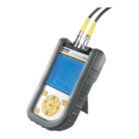
Analog + AUX model analog version
21 3 4
Fig.5 Connections, Analog + AUX model version
Pos. Designation Description
1 Analog connections
(IN1, IN2, IN3, IN4)
To connect Parker analog sensors with auto-
matic sensor detection
2 AUX connection To connect analog external sensors
3 USB-C connection For connection to the power supply adapter or
to a PC
4 USB-A connector To connect the USB memory stick
19
The Parker Service Master COMPACT V1.0/02/24
Design and Function