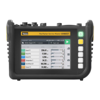
6.2 Display Layout
This chapter contains information on the basic display layout and the positions
of all display elements.
1 3 98
10
4
7
5 62
Fig.13 Display layout
Pos. Element Description
1 Status bar Display for system information
2 Information line Current menu position, name and duration
of the current measurement recording
3 Main view Display of the current function
4 Button Top-Down menu Opens the Top-Down menu
5 USB stick symbol USB stick is connected
6 Sensors symbol Sensor(s) connected, number of connect-
ed channels
7 Measuring methods menu
area
Selects Measuring methods
8 Button, Start/Stop To start/stop measurements
9 Menu Area To initiate the main functions
10 Options/Info button Measurement inactive: Display/hide Op-
tions menu
Measurement active: Displays sensor infor-
mation
30
The Parker Service Master COMPACT V1.0/02/24
Operation