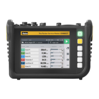
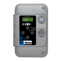
4.3 Connections
The following illustrations show the device connections for all model versions.
Detailed information on the connections and specifications is available in the fol-
lowing chapters.
CAN model version
2 31
Fig.3 Connections, CAN model version
Pos. Designation Description
1 CAN Bus To connect CAN bus sensors
2 USB-C connection For connection to the power supply adapter
or to a PC
3 USB-A connector To connect the USB memory stick
18
The Parker Service Master COMPACT V1.0/02/24
Design and Function