Peekel Instruments User manual PICAS V2.6.1
Page 10 of 59
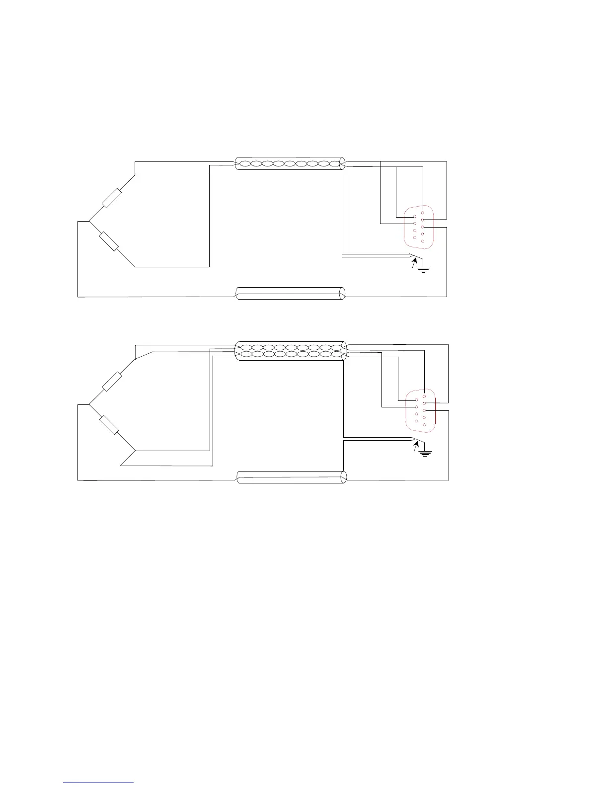
2.1.5 Half-bridge
Figure 2 shows half-bridge configured straingauges. The ½-bridge completion-resistors are
internally connected to -
IN
.
-EX
+EX
9 polig
male Sub D
+SE
-SE
5
9
6
1
Connect cable screen to
connector case.
Figure 4: Half bridge, 5-wire, straingauge-connection
The connection of the ½-bridge completion to -
IN
sets the amplifier for positive gain: so
connecting the +
IN
signal to +
EX
gives a positive outputsignal (although in overload).
Half-bridge connections are more critical than full-bridge. The leadwire-resistances in the
±
EX
-lines are in series with the 2 straingauges, in the Wheatstone bridge. Any slight
unbalance in these leadwire-resistances will give rise to signal-offset. Every 1mΩ difference
in resistance on a 120Ω bridge gives 2 µV/V offset. This may be compensated by use of the
internal balance circuit. However, temperature-influence can not be compensated. Short,
thick cabling is highly recommended