Peekel Instruments User manual PICAS V2.6.1
Page 15 of 59
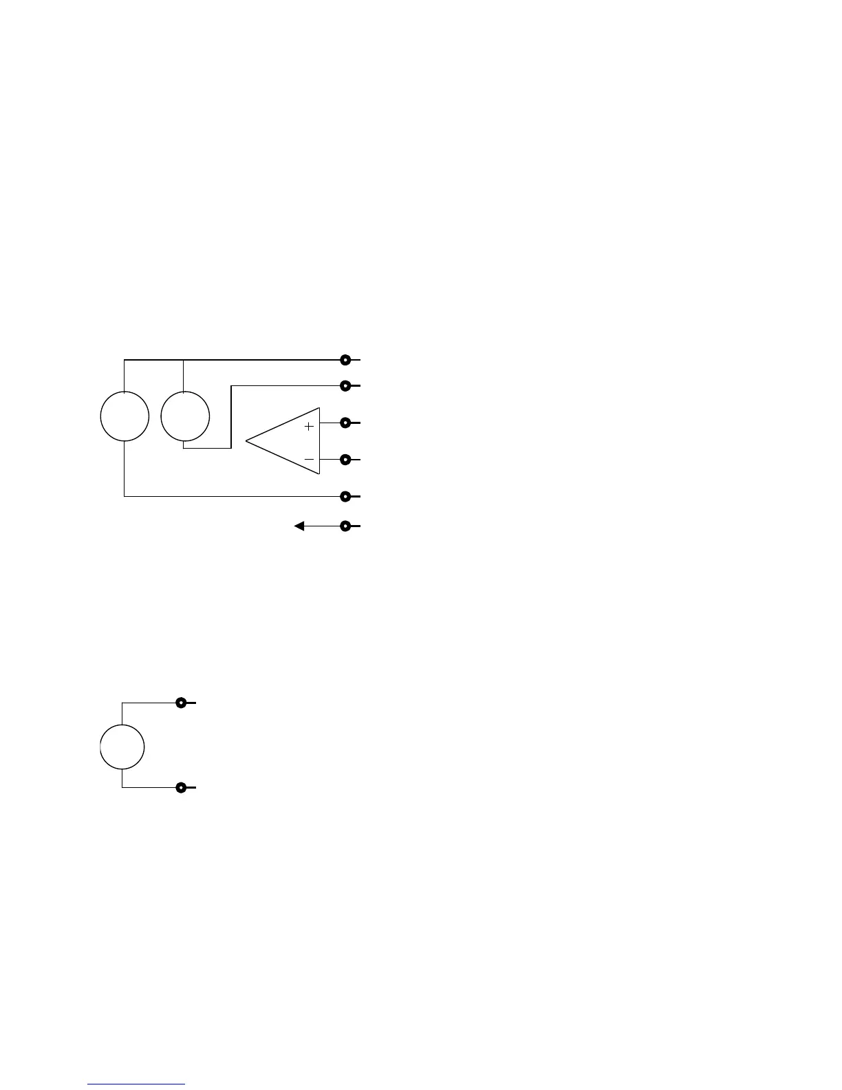
2.2.1 Analog input connector pinout
The following signals are present on the input connector:
pin 1 : + Supply voltage or current
pin 2 : - supply current
pin 3 : + IN (+ Input)
pin 4 : - IN (- Input)
pin 5 : - Supply voltage (0V)
pin 6 : Screen Ground
(Pin 1 is on the left side of each terminal, when one is looking at the rear site of PICAS.
Figure 11: Interne connection of the analog input
Connection pinout of the Power-terminal:
pin 1 : + 24VDC
pin 2 : - 24VDC
(Pin 1 is on the left side of each terminal, when one is looking at the rear site of PICAS.
Figure 12: Interne connection of the 24VDC supply
This power supply can deliver 80 mA maximum, and is galvanic isolated from PICAS.