Peekel Instruments User manual PICAS V2.6.1
Page 19 of 59
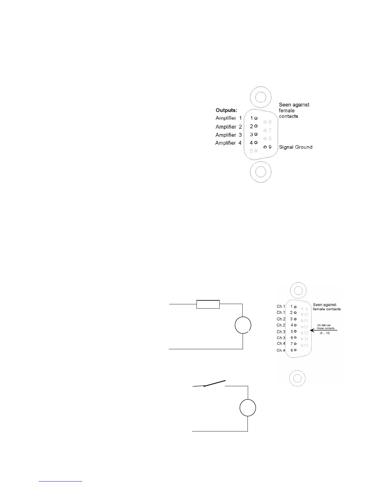
2.3 Outputs
2.3.1 Combined analog output
pin 1 : Amplifier output 1
pin 2 : Amplifier output 2
pin 3 : Amplifier output 3
pin 4 : Amplifier output 4
pin 5 : Screen gnd
pin 6 : Ground
pin 7 : Ground
pin 8 : Ground
pin 9 : Ground
Through these connections, all 4 outputs (0...+/-10 V)
are continuously available. They might be used for connecting an external multiplexer, or
other device.
Cable screen should be connected to the connector case. Do not connect to pin 5!
Individual analog outputs:
For each Carrier frequency channel, the same output voltage (0... +/-10 V) is also available
on a BNC connectors at the rear of the cabinet.
Note: The Channels from the CA4AI card do not have an analog output. Not on the board
itself and not on this combined analog output connector!!
2.3.2 Digital Outputs
Connection diagram for
channel 1. The other channels are
identical, just use other pins:
2.3.3 Digital Inputs
On the same connector 2 digital
inputs are present. These
inputs are connected through
optocouplers to the processor.
Pin 12
Pin 11
5 – 24VDC
Imax = 2 mA