EasyManua.ls Logo

Peekel Instruments PICAS - General Design Principles

Default Icon
59 pages
Print Icon
To Next Page IconTo Next Page
To Previous Page IconTo Previous Page
Loading...
Peekel Instruments User manual PICAS V2.6.1
Page 6 of 59
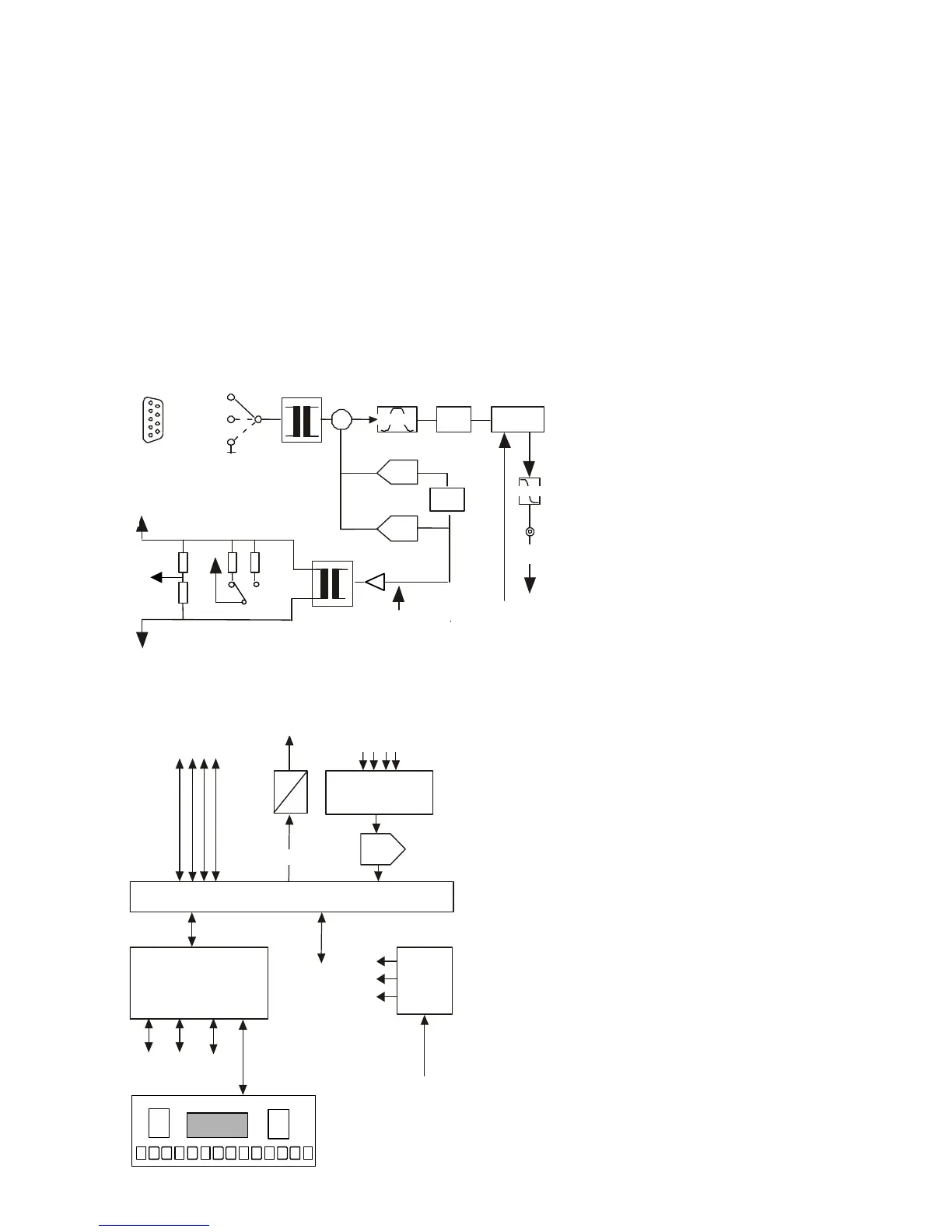
1.4 General design principles
The following drawings only show the basic principles of the carrier frequency amplifier, as
it is outside the scope of this user’s manual to go in full detail.
Basically, PICAS houses 1 controller board which controls the settings of the amplifiers as
well as the communication with external devices like a PC.
Also PICAS can hold up to 2 input cards, of the type CA2CF or CA4AI or a mix of those
cards.
The carrier frequency Amplifiers
gnd
-IN
+IN
+EX
-EX
1/4
+SE
-SE
IN
ZERO
9p M
Dsub
+
Analog
OUT
Phase
C-BAL
R-BAL
Demodulator
(Detector)
Bandpass
Phase
shifter
Gain-
control
Lowpass
125 uV/V .. 1V/V
Input
Control
5 KHz exc.ref.
Bridge completion
+ EX
-
EX
1/4
SE
240Ω
240Ω
120Ω
350Ω
-IN
The Controller board
The drawing shows the
evident advantage: the two
transformers, fully isolating
the measuring input from the
rest of the system.
The blockdiagram
shows the basic
elements of the central
processor module.
Further hardware
components.
Apart from the basic module,
the PICAS cabinet further
houses the power supply, the
LCD display-module, the front
with integrated pushbuttons and
a backpanel with various
input-
and output- connectors.
Analog
amplifiers
controls
5KHz
0.1234
Frontpaneel
Analog
signals
1 2 3 4
Multiplexer
Excitation
reference
FPGA
ADC
Power
regulator
Vin
Unstab.
Digital
sync.
Microprocessor,
Memory,
Communications
RS 232
RS 485
USB

Table of Contents