Peekel Instruments User manual PICAS V2.6.1
Page 11 of 59
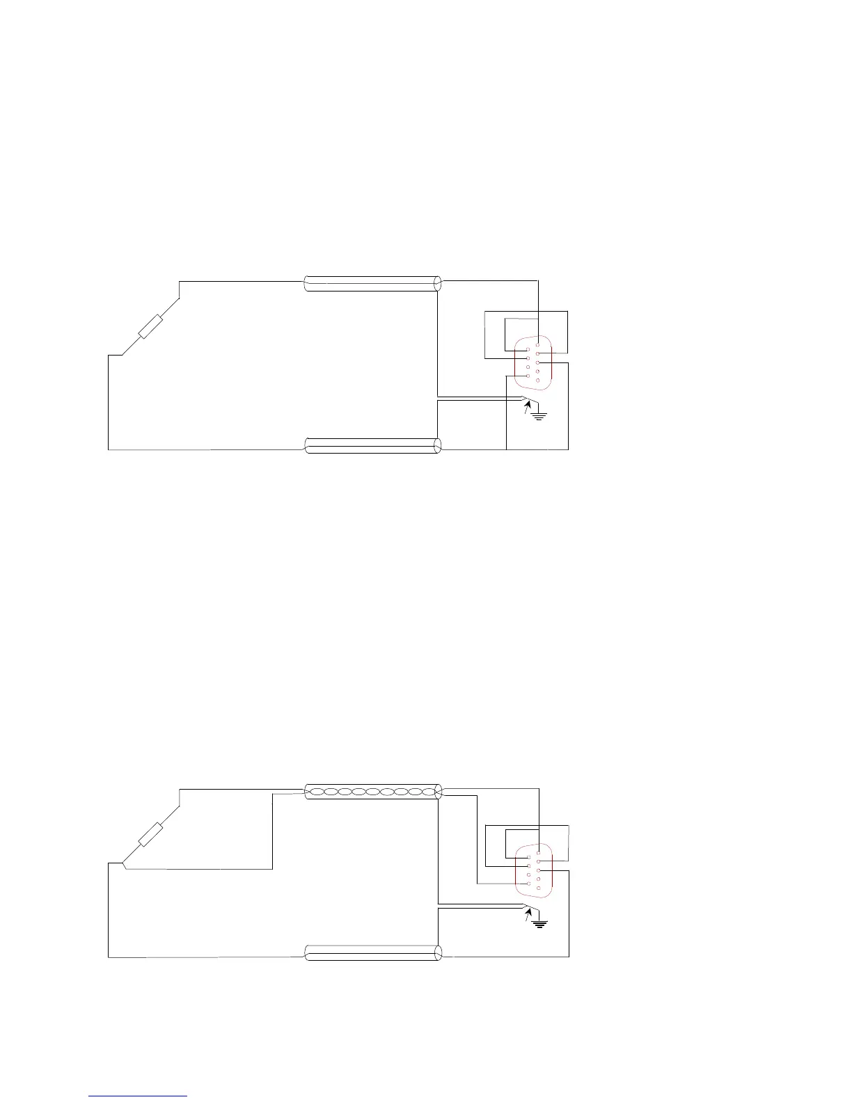
2.1.6 Quarter-bridge using 2-wires
Application of quarter-bridges is the simplest but least accurate way of measuring. The
leadwires in 2-wire configurations are completely incorporated in one arm of the
straingauge-bridge. Every 1 mΩ of cabling-resistance in series with a 120Ω straingauge, will
directly add 2 µV/V signal-offset, though in practical situations it is more likely to meet
several ohm’s of resistance
-EX
9 polig
male Sub D
5
9
6
1
Connect cable screen to
connector case.
Figure 5: Quarter-bridge, 2-wire, straingauge-connection
The internal balance-compensation range is 65 mV/V at 5 volt excitation. This allows for
1.25Ω total leadwire-resistance in series with a 120Ω straingauge. A bridge-voltage of 0.5
volt however gives a 10 times balance-range and enables 12.5Ω leadwire in series with a
120Ω straingauge.
The temperature-influence on the cable-resistance cannot be compensated. The
temperature- coefficient of copper of 0.4%/°C will give rise to 8.3 µV/V offset-change for
each Ω in series with a 120Ω straingauge. Short and thick cabling is evidently necessary!
2.1.7 Quarter-bridge using 3-wires
Most of the problems, mentioned before, can be avoided by using the 3-wire connection
method. It adds the resistance of the -
EX
-leadwire to the external straingauge, and it adds
the resistance of the wire leading to the internal ¼-bridge completion to this internal ¼-
bridge resistance. Only the difference in leadwire-resistance (and connector contact-
resistance) gives signal-offset.
-EX
9 polig
male Sub D
+SE