EASYTOUCH
®
PL4/PSL4 Control System Installation Guide
EASYTOUCH
®
PL4/PSL4 Control System Installation
17
WiringPentairUltraTemp
®
HeatPump
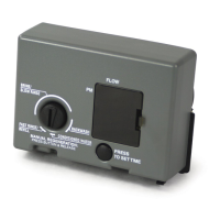
Be sure to check the UltraTemp Heat Pump terminal block conductor colors and pinouts (located on
the back of the Auto Set board) before connecting it to the EasyTouch
®
PL4/PSL4 Control System
COMport.TheSeethewiringtablebelowforthepinconguration.
IMPORTANT:OntheUltraTempheatpumpAutoSetcircuitboardONLYCONNECTPIN3(YELLOW)
andPIN2(GREEN)totheEasyTouchPL4/PSL4ControlSystemCOMportpinsYELLOWandGREEN
respectively.Donotconnectpin1orpin4ontheAutoSetboardortheCOMport.Thesepinsarenot
COMPortWireColor Descripion UltraTempHeatPumpPinNumberandWireColor
PIN 4 (RED) (DONOTUSE) +15 VDC
PIN4(DONOTUSE)
PIN 3 (YELLOW) + DATA PIN 3 (YELLOW)
PIN 2 (GREEN) - DATA PIN 2 (GREEN)
PIN 1 (BLACK) (DONOTUSE) GROUND
PIN1(DONOTUSE)
WiringIntelliFlo
®
Pumps
The RS-232 communication cable (provide with IntellliFlo pump) consists of a 50 ft 22 AWG four
conductorlowvoltagecable.TheEasyTouchPL4/PSL4ControlSystemlterpumpoutputisrated
at120VAC,15AMPmaximum.Checktheelectricalratingmarkedonthepumpmotorbefore
connecting it to the system.
To connect the IntelliFlo pump communication cable to the Power Center:
1. Switch AC power OFF to the Power Center at the main house circuit breakers.
2. Run the communication cable from the pump to the enclosure.
3. Insertthecableconductorsintotheoneoftheplasticgrommetttings,locatedonthe
lower left side of the enclosure and pull the cable up through the low voltage to the PL4/
EasyTouch PL4/PSL4 control system circuit board.
4. Strip back the outer jacket four (4) inches. Strip back each conductor a ¼-inch.
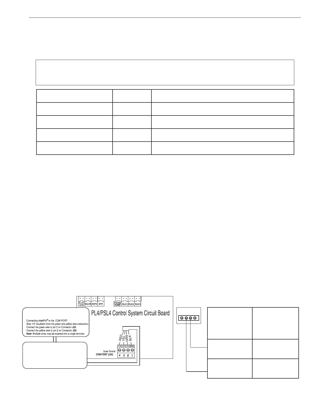
5. InserttheconductorsintotheCOMPort(J20) screw terminals located on the top of the
EasyTouch PL4/PSL4 Control System circuit board (see diagram below). Secure the
conductorswiththescrews.Forwiringdetails,refertothepincongurationshownbelow.
Note:Multipleconductorsmaybeinsertedintoasinglescrewterminal.
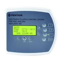
IntelliFlo Pump
COM Port
COM PORT - J20 connector: For IntelliFlo
®
Pump, iS4 Spa Side Remote QuickTouch
®
,
PL4/PSl4 Control System Indoor Control
Panel and Pl4/PSL4 Control System
Wireless Controller Transceiver.
J20
EasyTouch
PL4/PSL4
Control
System
COMPORT
Pinconguration
EasyTouch PL4/PSL4 Control
System
COMPORT(J20)
COM Port
screw
terminal
connector
IntelliFlo
(2-wire cable)
2 (GRN) GREEN (Pin 6)
3 (YEL)
YELLOW
(Pin 7)
 Loading...