34
EASYTOUCH
®
PL4/PSL4 Control System Installation Guide
PlumbingRequirements
It is important that the pool and spa plumbing system be in accordance with local codes and
the Recommended Hydraulic Schematics (page 36 and 37). Before starting, please review the
diagrams and the following recommended guidelines:
The spa should be at or above the level of the pool.
If the spa is attached to the pool, provide a dam between the two bodies of water to allow the
spatooverowintothepool.Ifthespaisnotattachedtothepool,anoverow,sufcientin
sizetocarryafullpump-ow,mustbeinstalledatthewaterlevelinthespa.
Plumbathree-portIntakeValveonthesuction-sideofthelterpump,sothatthecenterport
of the valve is connected to the pump inlet. Connect the spa suction to one side of the Intake
Valve, and the pool suction to the other side.
Plumb a three-port Return Valve on the return-side of the heater, so that the return water will
enter the valve through the center port.
Connect the spa return to one side of Return Valve, and the pool return to the other side.
If required, install a spa makeup line (consisting of a manual gate or ball valve, for elevated
spas install a check valve) to bypass the pool return line. This will enable some of the
chemically-balanced water from the pool to cycle through the spa. The manual valve will allow
the amount of bypass to be adjusted.
If the spa is to be constructed in concrete, special provision should be made at this time for
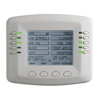
the installation of the Spa-Side remote control.
Select a convenient location in the deck or above water level in the spa wall (where the
Spa-Side remote will not be submerged by the spa water), and install a 6 in to 12 in length of
one inch PVC pipe to provide a receptacle for the Spa-Side remote. The pipe should be level
andprotrudebeyondthenishedsurfaceofthespa.Itwillbecutbacklateratinstallationtime.
Reducethepipesizedownto½inor¾inconduit,andrunittotheproposedLoad/Power
Center location at the equipment pad. Use sweep elbows for turns.
The Spa-Side remote will not be installed until the spa construction is completed.
For systems which incorporate a skimmer, it is possible to balance the amount of suction
between the skimmer and main drain for maintenance purposes. This is easily accomplished
by installing a manual three-port mixing valve at the suction line. Plumb one port to the
skimmer and the other to the main drain.
Ifa“non-boosterpump”pressure-sidepoolcleanerisbeingused,plumbamanualthree-
portvalvebetweenthelterpumpandlter,withthethirdportplumbedtothepoolcleaner
line,andinstallamotorizedtwo-portPoolCleanerValveatthisline.Themotorizedvalvewill
automatically open whenever the Control System activates the pool cleaner.
If a booster pump pool cleaner is being used, plumb the booster pump so that its suction-side
is connected to the pool return, after the heater, and as close to the ground as practical.
1
2
3
4
5
6
7
8
 Loading...