EASYTOUCH
®
PL4/PSL4 Control System Installation Guide
EASYTOUCH
®
PL4/PSL4 Control System Installation
25
EasyTouchPL4/PSL4ControlSystemQuickTouch
®
II
WirelessControllerTransceiverInstallation
InstallingtheQuickTouchWirelessControllerTransceiver
The following procedure describes how to install the EasyTouch PL4/PSL4 Control System
QuickTouch (QT4) Wireless Controller transceiver module and connect the transceiver cable to the
COMportonthemotherboard.Readthroughtheinstallationprocedurebeforestarting.
EasyTouchPL4/PSL4ControlSystemWirelessControllerkit
The EasyTouch PL4/PSL4 Control System wireless control panel kit consists of:
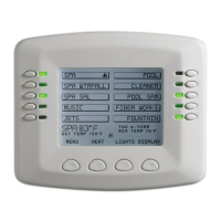
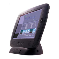
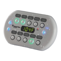
• EasyTouchPL4/PSL4wirelesscontrolpanel
• FourAA-sizealkalinebatteries
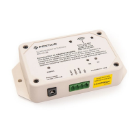
• Transceivermodule
• Fourplasticanchorsandretainingscrews(tomountthetransceivermodule)
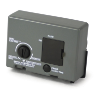
MountingtheWirelessTransceiver
The Transceiver is a two-way radio device with an attached antenna that communicates to and
from the EasyTouch PL4/PSL4 control system via the wireless hand-held wireless control panel.
MounttheTransceivermoduleataconveniencelocation(onaatverticalsurface)nearthePower
Center,ataminimumof5ft.abovegroundleveltooptimizethefunctionaloperatingrangeofthe
wireless control panel.
CAUTION-To avoid signal interference, mount the Transceiver antenna a minimum of
10 ft. away from the Power Center, any metal surface/structure, or air blower located in the
immediate area of the equipment pad.
To mount the transceiver near the EasyTouch PL4/PSL4 Control System Power Center:
1.
CAUTION-Switch the main power off at the EasyTouch PL4/PSL4 Control System
PowerCenter.
2. Remove the two retaining screws securing the transceiver case to the back plate.
Carefully slide the case off the back plate.
3.
CAUTION -ElectrostaticDischarge(ESD):Holdthecircuitboardfromtheedges.
Donottouchtheboardcomponents,electrostaticdischargecandamagetheboard.
Slide the transceiver circuit board up and out of the back plate.
4. Position the back plate against the mounting surface so that the case is oriented in
an upright position (with the antenna pointing upwards). Use a pencil to mark the four
mounting points. Drill four 3/16 in. diameter holes into the mounting surface. If screws are
not being used, insert the four plastic wall anchors (provided in the kit).
5. Feed the provided 10 ft. of UL approved four 22 AWG conductor cable through the
knockout hole at the bottom of the enclosure. Do not run wire through the drain holes. If
the knockout hole is not being used to run wire through, drill a hole through the bottom of
thebackplate,routethewirethroughtheholeandsealitusingattingwithafewfeetof
conduit or some other sealant between the case and the cable.

 Loading...