12
230 V
230 V
230 V
1
2
1
2
3
4
3
4
Radio
OFF
ON
CONDUCT
ORP
pH
+24 V
RS-485
+24 V
RS-485
BUS BUS
pH CL
Radio
OFF
ON
CONDUCT
ORP
pH
+24 V
RS-485
+24 V
RS-485
BUS BUS
pH CL
N L
AUX1
CL
230 V ~
BUS
24V
RS-485
pH
5-230 V~
OR
N L
AUX1
CL
230 V ~
BUS
24V
RS-485
pH
5-230 V~
OR
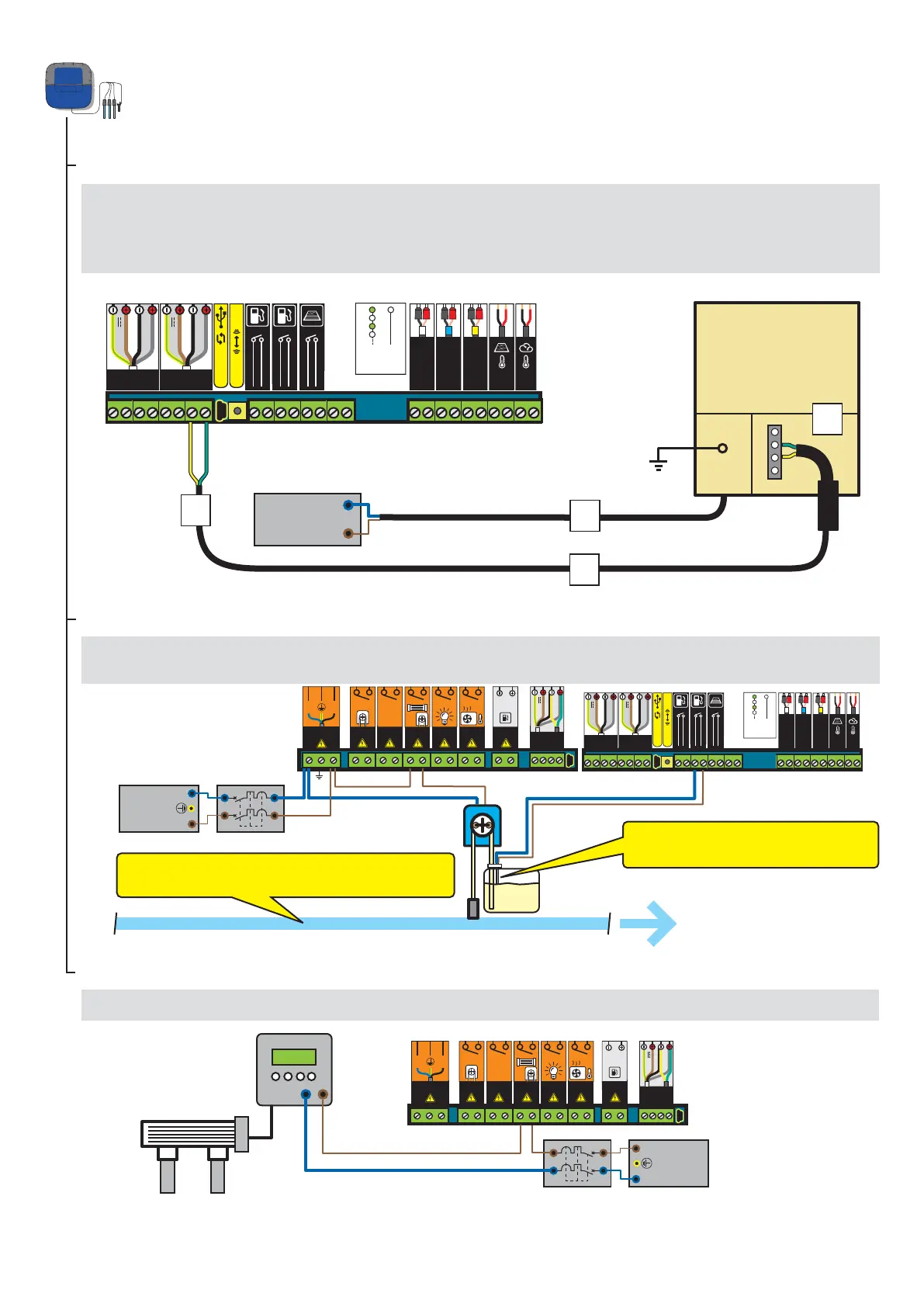
Connection of an IntelliChlor salt chlorinator
Connection of a liquid chlorine pump
1 - Connect the chlorine pump and the pH corrector level sensor as described below. Select “other” in the Settings/Install/Other menu, see p18.
The chlorine injection must be placed after filtration, after the heat pump
and after the probes.
1 - Connect the 230 V.
2 - Connect the IntelliFlo ref 350122/15-m cable supplied with IntelliPool
®.
3 - Connect the green cable to Datas+ and connect the yellow cable to Datas-.
4 - Connect the green strand on terminal 2 and the yellow strand on terminal 3 of the IntelliChlor
® Power Centre.
Connection of a disinfection system to the Probe Unit
Connection to a conventional salt chlorinator
1 - Connect a conventional electrolyser as described below.
Chlorine level sensor is normally open.
(Closed switch = empty tank)
Chlorine
EARTH
NEUTRAL (N)
PHASE (L)
EARTH
NEUTRAL (N)
PHASE (L)
NEUTRAL (N)
PHASE (L)
Communication
centre
for IntelliChlor ®