13
A2A1
230 V
230 V
3 bar min
pH -
pH+
230 V
230 V
Radio
OFF
ON
CONDUCT
ORP
pH
+24 V
RS-485
+24 V
RS-485
BUS BUS
pH CL
N L
AUX1
CL
230 V ~
BUS
24V
RS-485
pH
5-230 V~
OR
N L
AUX1
CL
230 V ~
BUS
24V
RS-485
pH
5-230 V~
OR
N L
AUX1
CL
230 V ~
BUS
24V
RS-485
pH
5-230 V~
OR
N L
AUX1
CL
230 V ~
BUS
24V
RS-485
pH
5-230 V~
OR
A1 A2
English
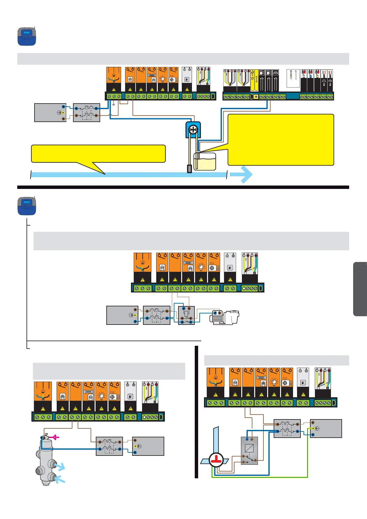
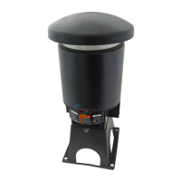
1 - Connect pH pump and the pH corrector level sensor as described below.
Connection of a pH pump to the Control Center
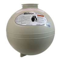
1 - Connect the pneumatic valve as described below.
Connection of a push/pull pneumatic valve
(automatic backwash) to the Control Center
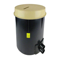
1 - Connect the 3-way valve as described below.
Connection of a 3-way valve
to the Control Center
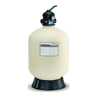
1 - Connect a second pump to the AUX1 outlet as described below.
Connection of the accessory pump to the Control Center
AUX1 connection (fountain or NAC or waterfall or garden lighting, etc.)
Chlorine level sensor is normally open.
(Closed switch = empty tank)
If an installation includes a pH pump and a chlorine
pump, the pool's two chlorine level sensors must be
connected serially.
The pH corrector must be placed after filtration, after the heating pump,
and after the probes.
English
To the lter
From the lter
EARTH
NEUTRAL (N)
PHASE (L)
EARTH
NEUTRAL (N)
PHASE (L)
EARTH
NEUTRAL (N)
PHASE (L)
EARTH
NEUTRAL (N)
PHASE (L)
L1
L2