9
4.4 Checking Motor Rotation
To check rotation before the pump is installed, follow
thesesteps:
During testing or checking rotation (such as “bumping”
or “inching”) the number of “starts” should be limited to
3and total run time of less than 15 seconds.
Bumping must be done while motor is in horizontal
position and followed by a full 15 minute cooling-off
period before any additional “starts” are attempted.
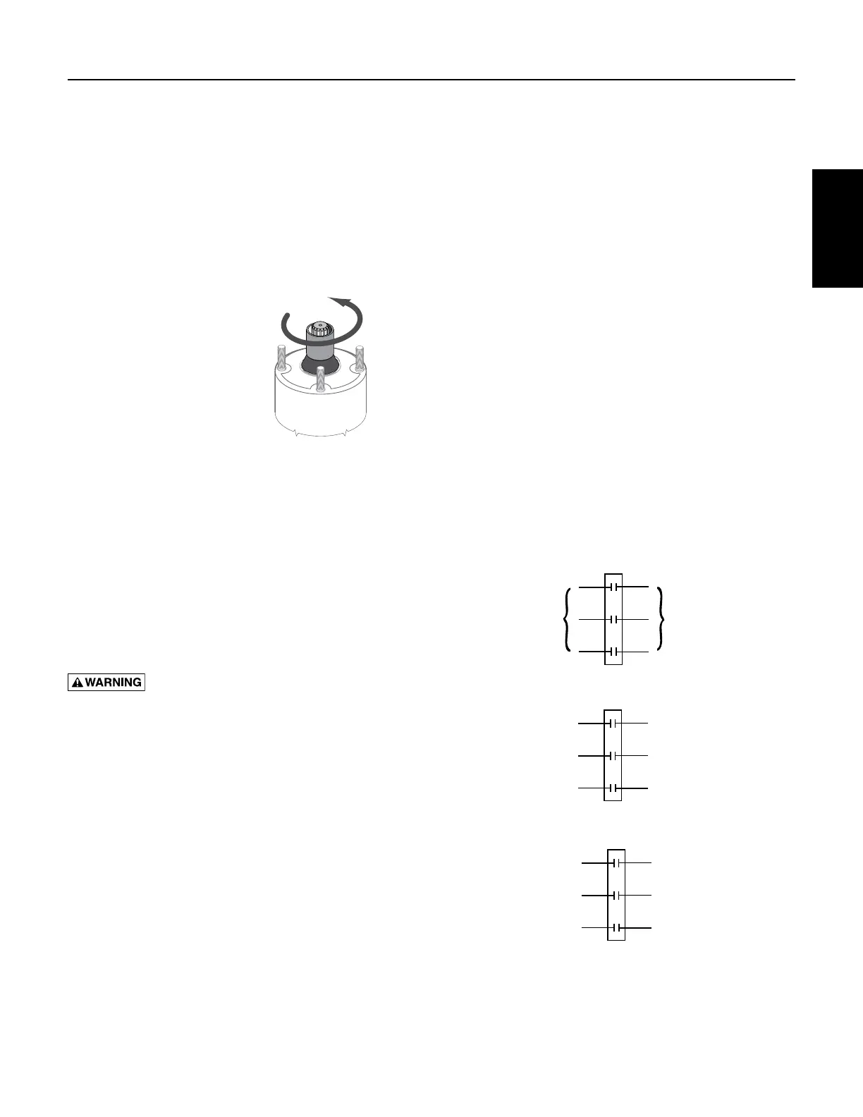
Energize the motor
briefly, and observe the
direction of rotation.
It should be counter-
clockwise when viewed
from the pump (shaft)
end.
To check rotation after
the pump is installed:
NOTICE: NEVER
continuously operate a
pump with the discharge
valve completely closed
(dead head). This can overload the motor due to lack of
cooling, or destroy the pump and will void the warranty.
After energizing the motor, check the flow and pressure
of the pump to make sure that the motor is rotating in the
correct direction. To correct a wrong rotation, switch any
two of the three cable connections (three-phase motor
only). The setting that gives the most flow and pressure is
correct.
A cooling-off period of 15 minutes is required
betweenstarts.
Hazardous voltage. Disconnect power
before working on wiring.
Input voltage, current and insulation resistance values
should be recorded throughout the installation and
should be used for preventive maintenance.
4.5 3-Phase Current Balancing
Current Unbalance Test
Before checking for current unbalance, the pump must
be started, and rotation direction determined.
Determine current unbalance by measuring current in
each power lead. Measure current for all three possible
hookups (Figure 4-11). Use example and worksheet on
the Installation Checklist and Record in Section 12 to
calculate current unbalance on a three phase supply
system and retain for future reference.
NOTICE: Current unbalance between leads should not
exceed 5%. If unbalance cannot be corrected by rolling
the leads, locate the source of the unbalance.
Here is an example of current readings at maximum
pump loads on each leg of a three wire hookup. Make
calculations for all three possible hookups.
A. For each hookup, add the readings for the three legs.
B. Divide each total by three to get average amps.
C. For each hookup, find current value farthest from
average (Calculate the greatest current difference
from the average).
D. Divide this difference by the average and multiply by
100 to obtain the percentage of unbalance.
Use smallest percentage unbalance, in this case
Arrangement 2 (Table 4.1).
Us e the Current-Balance worksheet
located in the Installation Record
After trying all three lead hookups, if the reading furthest
from average continues to show on the same power lead,
most of the unbalance is coming from the power source.
Call the power company.
If the reading furthest from average changes leads as the
hookup changes (that is, stays with a particular motor
lead), most of the unbalance is on the motor side of the
starter. This could be caused by a damaged cable, leaking
splice, poor connection, or faulty motor winding.
SECTION 4: Electrical Power
Figure 4-10: Motor Rotation
Starter
Electrical
Power
Supply
To Motor
L1
L2
L3
T1
T2
T3
Starter
L1
L2
L3
T1
T2
T3
Arrangement 1
Starter
L1
L2
L3
T1
T2
T3
Arrangement 2 Arrangement 3
Starter
Electrical
Power
Supply
To Motor
L1
L2
L3
T1
T2
T3
Starter
L1
L2
L3
T1
T2
T3
Arrangement 1
Starter
L1
L2
L3
T1
T2
T3
Arrangement 2
Starter
Electrical
Power
Supply
To Motor
L1
L2
L3
T1
T2
T3
Starter
L1
L2
L3
T1
T2
T3
Arrangement 1
Starter
L1
L2
L3
T1
T2
T3
Arrangement 2
Arrangement 3
Figure 4-11: 3-Phase Current Unbalance: Example
Electrical Power
 Loading...