105
SECTION 14: Appendix
14.6 Record of Installation
Outside Power:
Transformer 1 KVA
Transformer 2 KVA
Transformer 3 KVA
Cables
From Service Entrance to Pump Control:
Size AWG/MCM
Length ft.
Temp. Rating °F / °C (circle one)
Check appropriate boxes
❏ Copper ❏ Aluminum
❏ Jacketed ❏ Individual Conductors
From Pump Control to Motor:
Size AWG/MCM
Length ft.
Temp. Rating °F / °C (circle one)
Check appropriate boxes
❏ Copper ❏ Aluminum
❏ Jacketed ❏ Individual Conductors
Pump Motor Control Panel
Manufacturer / Model
Circuit Protection:
❏ Circuit Breaker: Amps
❏ Fuse Amps
❏ Std. ❏ Delay
Starter
Manufacturer Size
Type
❏ Autotransformer
❏ Full Voltage
❏ Other
Time to full voltage sec.
Heaters
Manufacturer
Qty: Amp setting
Installation Data
Controls grounded to:
❏ Motor ❏ Well Head
❏ Power Supply ❏ Buried Rod
Grounding wire size AWG / MCM
Date
Location
Motor serial number:
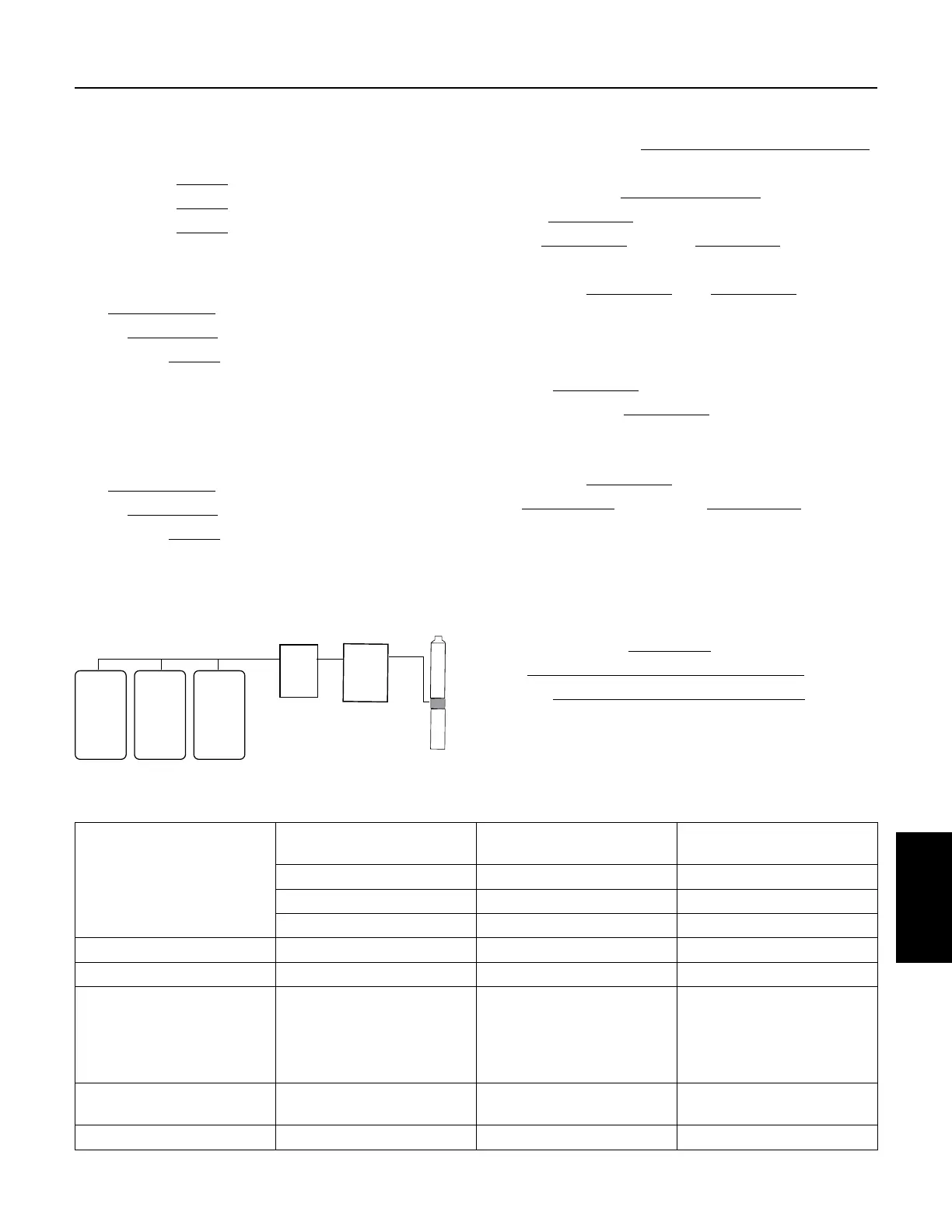
T1 T2 T3
Service
Entrance
Transformers
Pump
Control
Pump
Assemb
Motor Current - Balance Worksheet
Arrangement 1
Amps
Arrangement 2
Amps
Arrangement 3
Amps
L1–T1 = L1–T3 = L1–T2 =
L2–T2 = L2–T1 = L2–T3 =
L3–T3 = L3–T2 = L3–T1 =
Total Amps
Average Amps
From Average Amps
Deviation L1
Deviation L2
Deviation L3
————
————
————
————
————
————
————
————
————
% Current Unbalance
Largest Deviation
% Unbalance + % % %
Appendix
 Loading...