104
SECTION 14: Appendix
EXAMPLE
Assume we want 16 GPM at 60 PSI from a pump
drawdown level (pumping level) 100 feet below the
serviceinlet.
We have a 35 foot horizontal run of 1 1/4” plastic pipe
with two gate valves and four 90° elbows.
To find the Friction losses we must refer to friction loss
charts for pipe and fittings.
We find:
• 135feetofpipeforthetotalpiperun(100+35).
• 10equivalentfeetofpipeforthegatevalves(2x5)
• 28equivalentfeetofpipefortheelbows(7x4)
Add these for the total equivalent length of pipe = 173
• Inthefrictionlosscharts,findthelossofheadfor
173feet of 1 1/4” pipe at 16 gpm. (3.96 per 100’) =3.96
x 1.73 = 6.8 (round to 7.0)
Add: 7 Friction loss
100 Pumping level
139 60 PSI service pressure required (60
x2.31=138.6. Round to 139)
= 246 Total Dynamic Head.
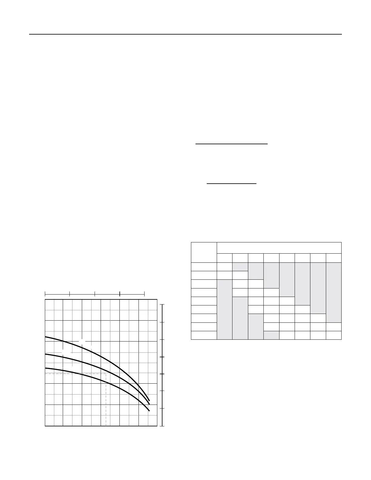
From this sample curve we would choose the
11/2HPpump.
Locate a pump with a best efficiency point near the
desired flow rate (16 GPM) that meets the total head
requirements (246 TDH).
Selecting a pump in this manner gives you the most
efficient pump for your application.
14.5 Sizing Tanks
Tank should be sized to accomodate starting frequency in
Section 5.10.
Refer to the dealer catalog for tank selection. Otherwise,
the following procedure can be used.
Drawdown based on Boyle’s Law
Procedure:
1. Identify drawdown multiplier relating to
specific application.
2. Insert multiplier (X) into the following formula:
Pump GPM x Min Run Time = Minimum Tank
Multiplier (X) Capacity Required
Example: An example of a 20 GPM pump with a
minimum run time of 1 minute, installed on a
50-70 PSIG system pressure range:
20 GPM x 1 minute = 83.3 minimum U.S.
.24 (factor) gallon tank capacity
NOTICE: Drawdown will be affected by operating
temperature of the system, accuracy of the pressure
switch and gauge, the actual pre-charge pressure and the
rate offill.
Table 12-2: Drawdown Volume Multiplier
(Approximate)
Pump Off
Pressure
PSI
Pump Start Pressure –PSI
10 20 30 40 50 60 70 80
20 0.26
30 0.41 0.22
40 0.37 0.18
50 0.46 0.31 0.15
60 0.40 0.27 0.13
70 0.47 0.35 0.24 0.12
80 0.42 0.32 0.21 0.11
90 0.48 0.38 0.29 0.19 0.10
100 0.44 0.35 0.26 0.17
Ta nk sizing for Variable Frequency Drives
Variable Frequency Drives (VFD) may require slightly
different methods for figuring tank size. Refer to
Section 8 for VFD information.
Sample Pump Curve
600
500
400
300
200
100
0 20 10 5 25 30 15
1 HP
1-1/2 HP
2 HP
CAPACITY GALLONS PER MINUTE
CAPACITY LITRES PER MINUTE
TOTAL HEAD IN METERS
25 0 50 75 100
175
150
125
100
75
50
25
0
 Loading...