70
9.4 Wiring Connections
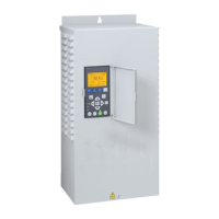
Three phase input power is connected to U1, V1, and W1.
If single phase input is used connect to U1 and W1. The
neutral and ground leads must be connected to drive
terminal PE. Motor leads are connected to U2, V2, and
W2. The motor ground must be connected to terminal
GND. For detailed instructions, see Owner’s Manual.
9.5 Transducer Connection
The Pentek
®
Assistant defaults to a 4-20mA transducer
connected to AI2. The transducer is used to provide
pressure feedback to the drive. Transducers offered
by Pentek have either a red or brown power lead. The
red or brown lead should be connected to the +24V
powerconnection.
Transducers offered by Pentek have either a blue or black
output lead. The blue or black lead should be connected
to terminal 5. The Pentek U17-1286R transducer utilizes
shielded cable. The bare lead may be covered with green
shrink-wrap tubing. The bare lead is cable shielding, and
should be connected to terminal 1. The translucent lead
is unused, and should be tied off andinsulated.
Figure 9-3 PPC3 Transducer Connection.
4 - 20 ma Output
Jumper Board
Power Lead
DIP Switches
+24 volt
Power
Connection
Figure 9-4 PPC5 Transducer Connection.
U1/L V1-N W1 BRKBRK U2 V2 W2
Digital Output
5405 0506
Relay Output
Digital Inputs
Analog I/O
Output to Motor
U2, V2, W2
Line Input
U1, V1, W1
Figure 9-1 Typical Connections to PPC3
Power
Output
to Motor
U2, V2, W2
Line Input
U1, V1, W1
Ground
Figure 9-2 Typical Connections to PPC5
SECTION 9: PPC Series 50/60 Hz Variable Frequency Drives
 Loading...