52
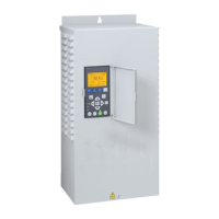
SECTION 8: Pentek Intellidrive
™
Variable Frequency Drives
Mounting the Drive
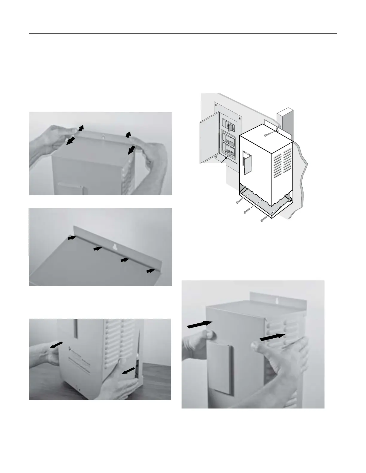
To mount the Drive as shown in Figure 6, follow
this procedure:
1. First, remove the cover by backing out screw
at bottom of front cover.
2. Push on backplate with thumbs while pulling
the cover toward you with index fingers,
creating a gap. See Figures 3 and 4.
3. Pull bottom of cover towards you; lift up on
cover and remove. See Figure 5.
4. With the cover removed, permanently mount
the Drive using the top slotted hole, plus
either the three bottom holes (for flat surface
mounting) or the center bottom hole (for
attaching to a post or stud). See Figure 6.
Gap
Figure 3 - Separate cover and backplate
Figure 4 - Gap between cover and
backplate
Figure 5 - Pull out bottom of cover
5. Ensure the Drive’s ventilation holes are
not blocked and there is enough space
around it to allow free air flow (minimum
3” clearance on top, bottom, and sides).
See Figure 6. Once the Drive is mounted,
electrical wiring can be connected.
6.
To r
eattach the Drive cover, hook the top of it
on backplate (be sure to leave a gap). Lower
bottom of cover into place. Push cover evenly
against backplate, eliminating the gap. See
Figure 7.
7.
Replac
e screw at bottom of front cover.
Figure 6 - Attaching Drive to wall
Typical
230VAC
Circuit
Breaker
(Double
Width)
Figure 7 - Reattaching Drive cover

 Loading...