IVIS
®
Lumina XRMS Series III Hardware Manual Chapter 7 | Basic Operation 50
2. Remove the locking screw using the hex wrench provided with the imaging system (Figure 7.8).
3. Slide the scintillation plate out by pulling the plate toward you.
The magnets and alignment pins on the scintillation plate are visible after the plate is removed
from the scintillation assembly. The scintillation assembly has matching magnets and pin
receptacles (Figure 7.9).
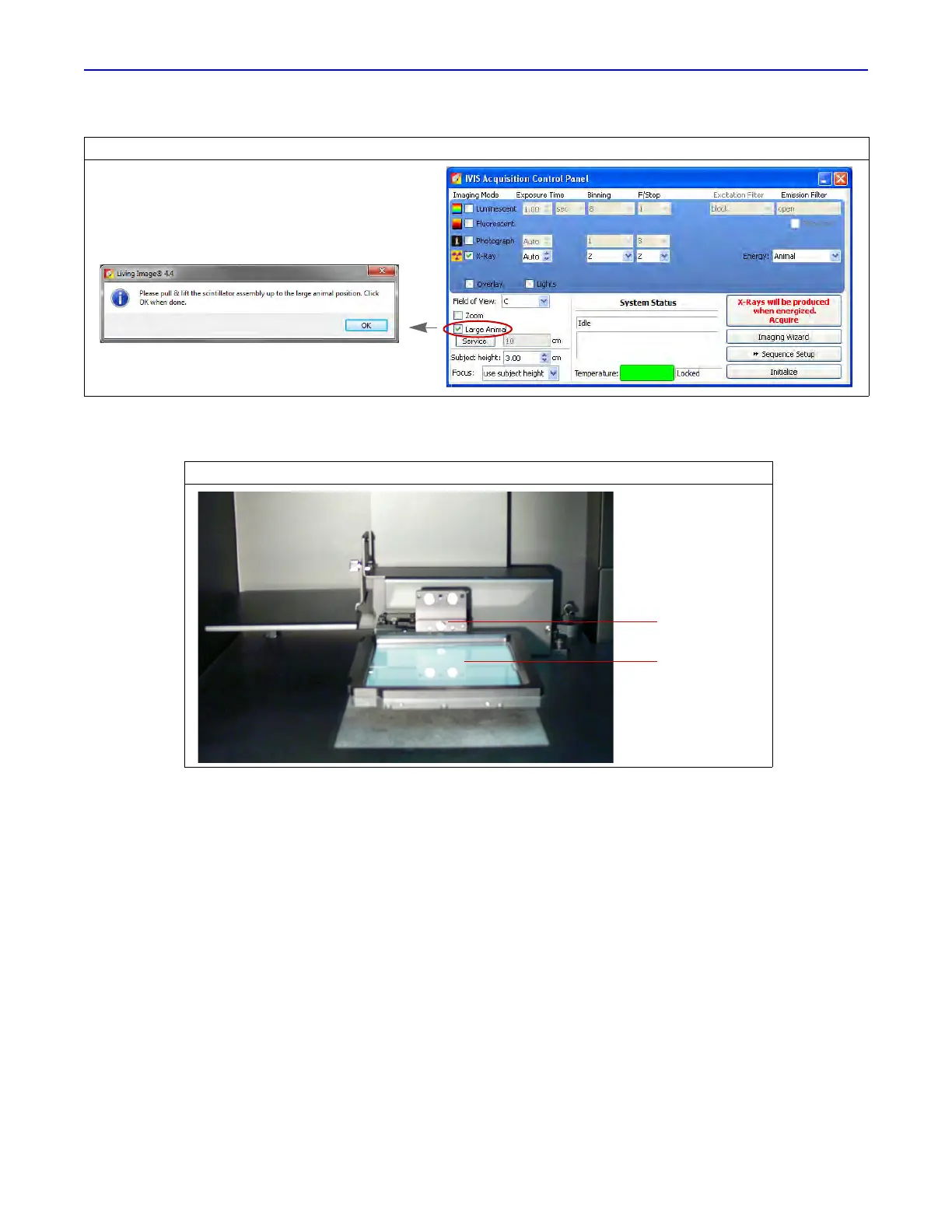
Figure 7.7 Control Panel
Figure 7.8 Remove the Locking Screw
Locking screw
Scintillation
plate
 Loading...