IVIS
®
Lumina XRMS Series III Hardware Manual Chapter 7 | Basic Operation 51
4. Place the scintillation plate in the upper position using the alignment pins and magnets as guides
(Figure 7.10).
5. Reinstall the locking screw.
6. Move the scintillation plate cover to the upper position.
a. Loosen the thumb screw (Figure 7.11).
b. Remove the cover by pulling the alignment pins of the cover out of the scintillation assembly.
c. Place the cover in the upper position using the alignment pins as guides.
d. Tighten the thumb screw.
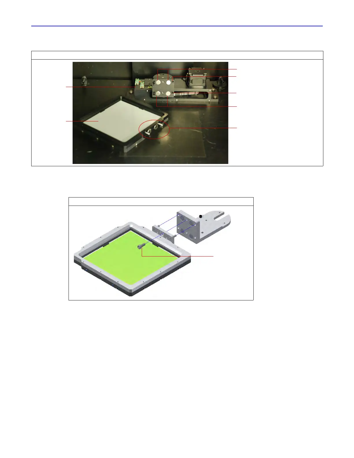
Figure 7.9 Alignment Pins and Magnets
Figure 7.10 Placing the Scintillation Plate in Upper Position
Alignment pins and magnets
Magnets – upper position
Magnets - lower position
Right alignment pin receptacle –
upper position
Right alignment pin receptacle –
lower position
Scintillation
assembly
Scintillation
plate
 Loading...