IVIS
®
Lumina XRMS Series III Hardware Manual Chapter 7 | Basic Operation 53
3. Slide the scintillation plate out by pulling the plate toward you.
After the plate is removed from the scintillation assembly, magnets and alignment pins on the
scintillation plate are visible. The scintillation assembly has matching magnets and pin
receptacles (see Figure 7.9 on page 51).
4. Place the scintillation plate in the lower position using the alignment pins and magnets as guides
(Figure 7.14).
5. Reinstall the locking screw.
6. Move the scintillation plate cover to the lower position.
a. Loosen the thumb screw (Figure 7.15).
b. Remove the cover by pulling it off the alignment pins.
c. Place the cover in the lower position using the alignment pins as guides.
d. Tighten the thumb screw.
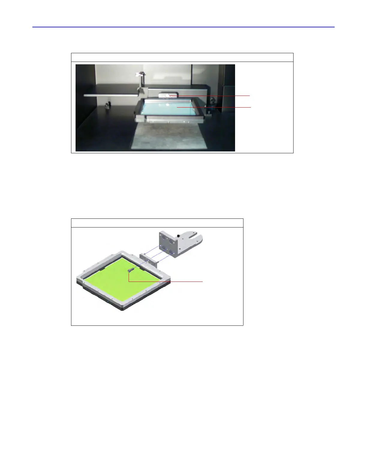
Figure 7.13 Remove the Locking Screw
Figure 7.14 Placing the Scintillation Plate in the Lower Position
Locking screw
Scintillation
plate
 Loading...