AxN Configurable Motion Control Platform
55
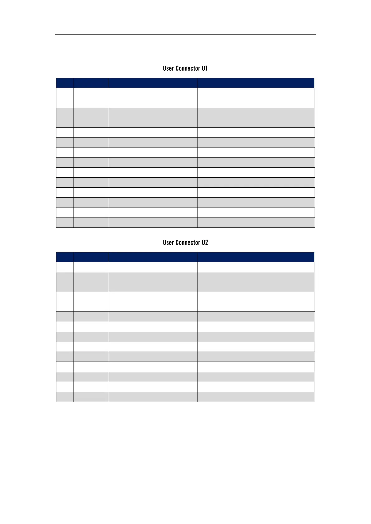
Pin Assignment
Programmable analog input
±10V, Zin=10KΩ, able to switch between
differential mode and single end mode
(1)
Programmable analog input
±10V, Zin=10KΩ, able to switch between
differential mode and single end mode
(1)
Programmable analog output
Programmable digital input
6.6 kΩ to ground, 20-30 V
Programmable digital input
6.6 kΩ to ground, 20-30 V
Programmable digital input
6.6 kΩ to ground, 20-30 V
Programmable digital input
6.6 kΩ to ground, 20-30 V
Programmable digital output
PNP open collector, 24 V, 100mA max
Programmable digital output
PNP open collector, 24 V, 100mA max
Programmable analog input
±10V, Zin=10KΩ, able to switch between
differential mode and single end mode
(1)
Programmable analog input
±10V, Zin=10KΩ, able to switch between
differential mode and single end mode
(1)
Programmable analog output
Programmable digital input
6.6 kΩ to ground, 20-30 V
Programmable digital input
6.6 kΩ to ground, 20-30 V
Programmable digital input
6.6 kΩ to ground, 20-30 V
Programmable digital input
6.6 kΩ to ground, 20-30 V
Programmable digital output
PNP open collector, 24 V, 100mA max
Programmable digital output
PNP open collector, 24 V, 100mA max
Auxiliary supply negative
Notes:
1. AxN 09.20.4 Drive has 4 single end analog inputs or 2 differential analog inputs, and they can
be switched by software. The default mode is differential mode. When analog inputs are in
differential mode, pin R0P (U1-1) and pin R0N (U1-2) map the R0 channel in software, and pin
R1P (U2-14) and pin R1N (U2-15) map the R1 channel in software. On the other hand, when
analog inputs are in single end mode, pins: AI0 (U1-1), AI1 (U1-2), AI2 (U2-14) and AI3 (U2-15)
respectively map channels AI0, AI1, AI2 and AI3 in software.