81
13. DDC Instruction
General
DDC Data Re-programming
In case the main EEPROM with Software DDC which store all factory settings were replaced for a defect, the serial
numbers of the repaired monitor have to be re-programmed.
It is advised to re-solder the main EEPROM with Software DDC from the old board onto the new board if circuit
board has been replaced, in this case the DDC data does not need to be re-programmed.
Additional information about DDC (Display Data Channel) may be obtained from Video Electronics Standards
Association (VESA). Extended Display Identification Data (EDID) information may be also obtained from VESA.
1. An i486 (or above) personal computer or compatible.
2. Microsoft operation system Windows 95/98/2000/XP.
3. “PORT95NT.exe”, “TPVDDC5.6.exe”, “TPVHDMI.exe” program.
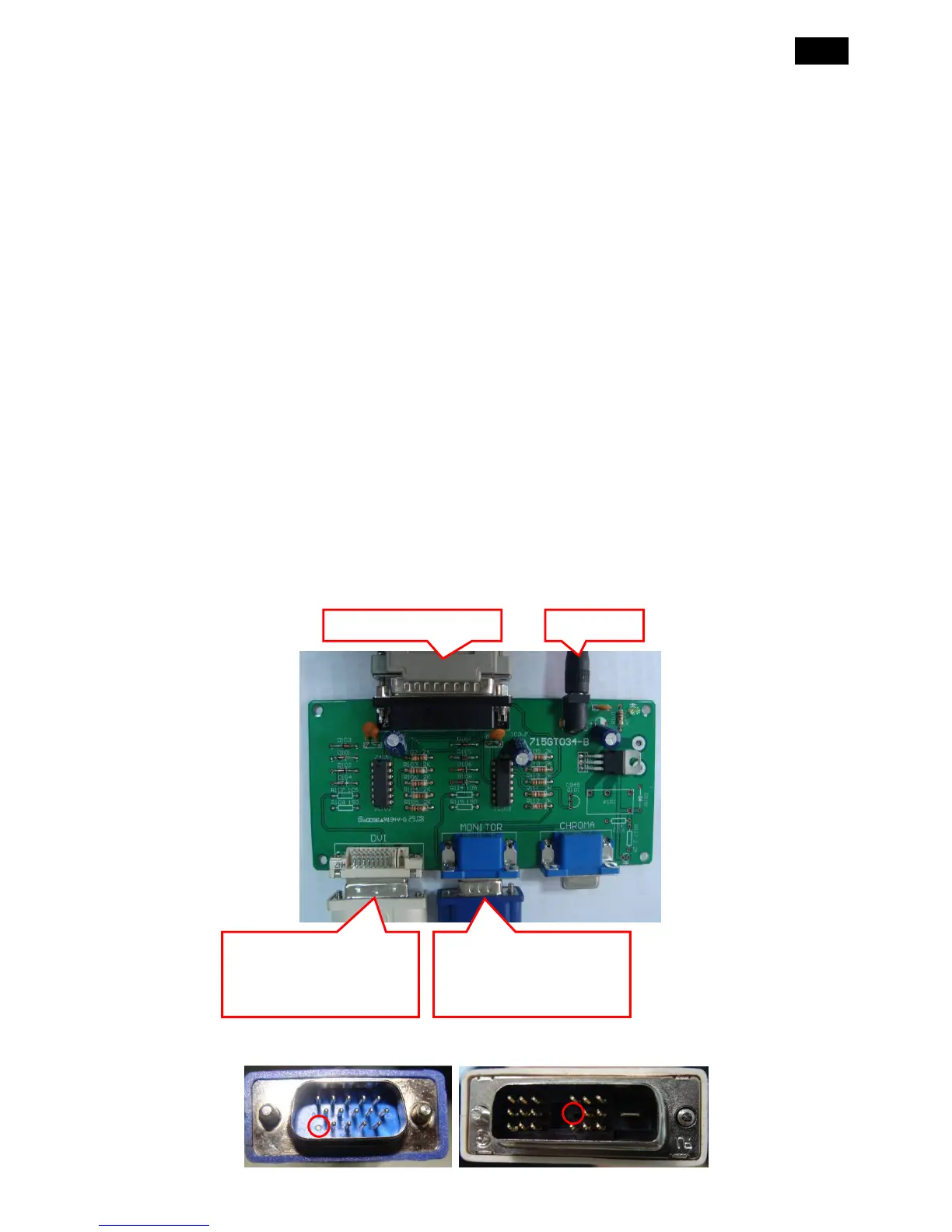
4. DDC BOARD (715GT034-B) x1
5. Printer cablex1, VGA cable x 1, power cord x 2, 12V DC power source
6. EDID Data
13.1. Install the “PORT95NT.EXE”, and restart the computer.
The process of installing “PORT95NT” has been specified in, so it will not be specified again. If you have any
problem, please read it.
13.2 Connect the DDC Board as follow:
Note: Cut off the 5th pin of the analog connector and 14th pin of the digital connector, as follow:
Connect to the PC LPT
12V Input
When you write analog
EDID, Connect this port to
the Phili