Mechanical Instructions
EN 13JL2.1E AA 4.
At the same time, use a screwdriver to carefully prize the
shielding at the bottom side [4], and remove the shielding.
The SSB is now accessible.
4. To remove the whole SSB, unscrew all connector fixing
screws from the connector plate [5] + [6] + [7]. Use a 5 mm
socket screwdriver to remove both DVI connector distance
bolts [6].
5. Disconnect the LVDS cable, and all other cables.
6. Remove the mounting screw [8] from the SSB.
7. Bend the brackets [9] away (may require some force), lift
the SSB, and take it out.
4.3.10 SCART Panel
1. Disconnect all cables from the panel.
2. Remove the mounting screws [7] beside the SCART
connectors at the connector plate (see figure” Connector
plate").
3. Take out the SCART panel.
4.3.11 Digital Media Reader
1. Disconnect the USB cable at the SSB and the power line at
the Stand-by/Audio panel.
2. Remove all mounting screws from the module.
3. Take out the module (replace complete module if defect).
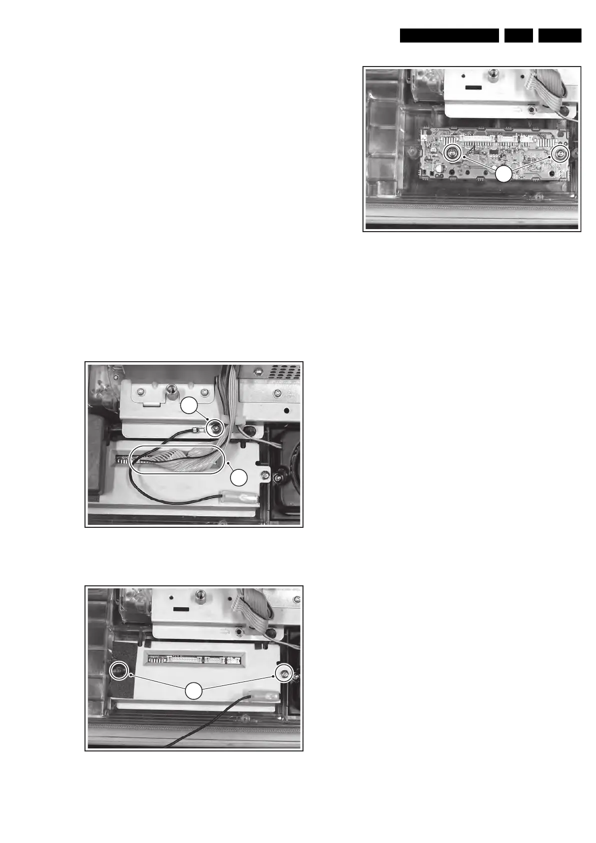
4.3.12 LED Panel
Figure 4-18 LED panel (part 1)
Figure 4-19 LED panel (part 2)
Figure 4-20 LED panel (part 3)
1. Disconnect all cables from the LED panel [1][2].
2. To access the mounting screws you have to remove the
Digital Media Reader.
3. Remove the shielding mounting screws [3]: one of them is
hidden under a piece of tape.
4. Take out the panel.
4.3.13 Woofer
1. Remove all mounting screws.
2. Take out the woofer unit together with its cable.
Caution: the woofer unit must remain airtight.
4.3.14 Side I/O Panel
1. Disconnect all cables from the panel.
2. Remove all mounting screws (if present) from the panel.
3. Slide the bracket to the right.
4. Release the clamp and take out the panel.
F_15710_141.eps
190905
2
1
F_15710_142.eps
190905
3
F_15710_143.ep
19090
4