Mechanical Instructions
EN 12 JL2.1E AA4.
4.3.5 Top Control
1. Disconnect all cables from the panel.
2. Remove all mounting screws from the panel.
3. Release the clamps and take out the panel.
4.3.6 Stand-by Supply / Audio Amplifier Panel
1. Disconnect all cables from the panel.
2. Remove all mounting screws from the panel.
3. Take out the panel (it hinges at the bottom side).
4.3.7 DC/DC Interface Panel (only for 32” model)
1. Disconnect all cables from the panel.
2. Release the clamps and take out the panel.
4.3.8 Main Supply Panel
1. Disconnect all cables from the panel.
2. Remove all mounting screws from the panel.
3. Take out the panel (it hinges at the right side).
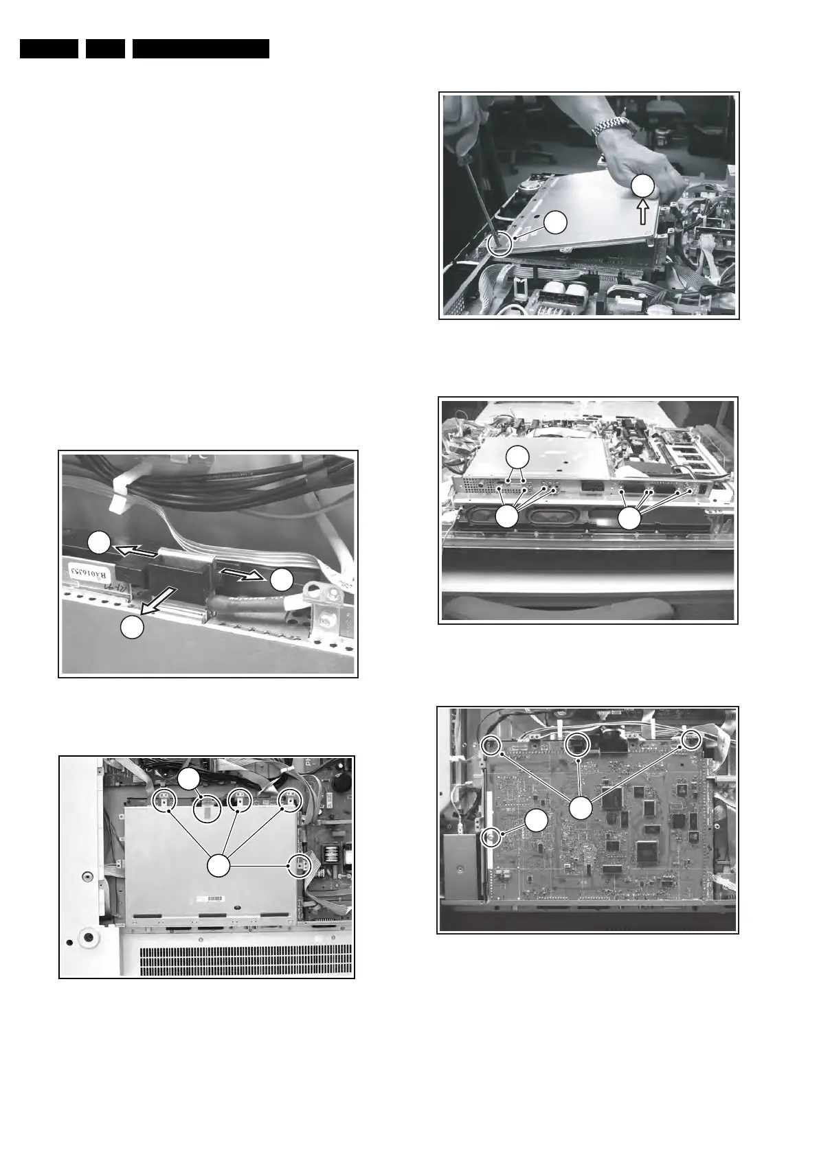
4.3.9 SSB
Figure 4-13 LVDS connector locking bracket
Figure 4-14 SSB top shielding screws
Figure 4-15 SSB top shielding
Figure 4-16 Connector plate
Figure 4-17 SSB brackets
1. 1st Figure: Remove the LVDS connector locking bracket
[1], [2].
2. 2nd Figure: Remove all shielding fixing screws [2].
3. 3rd Figure: Slide, and lift the shielding at the top [3] (Note:
in some cases a piece of tape is used at the left underside
of the SSB. This tape must be cut or removed before you
can lift the shielding). The panel hinges at the SCART side.
F_15490_017.eps
240605
1
1
2
E_14620_030.eps
130504
1
2
F_15490_015.eps
230605
4
3
F_15710_144.eps
200905
5
7
6
F_15490_027.eps
240605
9
For
PDP
8