Circuit Descriptions, Abbreviation List, and IC Data Sheets
EN 201JL2.1E AA 9.
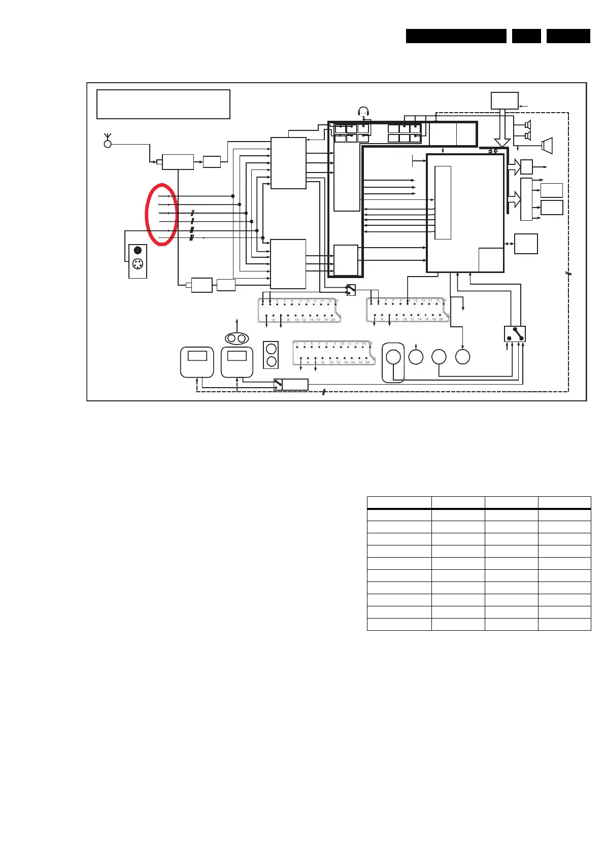
Figure 9-2 Audio Block Diagram
The AVIP together with the MPIF device is used to perform the
input decoding of a single stream of analog audio and video
broadcast signals. In addition, the AVIP is used for decoding
and presentation of audio output streams. The main data
connection between MPIF and AVIP is done via an I
2
D bus.
The AVIP converts the incoming video data to ITU-656 format
for communication to the VIPER IC.
The audio data is transferred between the AVIP and VIPER
using I
2
S.
The AVIP IC is controlled by the VIPER via the I
2
C bus.
The key component in the system, the VIPER, performs almost
all key features, like video quality enhancement, motion
compensation, picture-in-picture processing, and others. It is a
completely digital IC with a TriMedia DSP (Digital Signal
Processor) core and a MIPS microcontroller core. The DSP
and some additional cores are used to do the video feature
processing and some auxiliary sound feature processing. The
MIPS microcontroller core is used for all internal and external
controlling tasks including a system wide I
2
C bus.
Connected to the VIPER (via the tunnel bus of the PNX2015)
is the SPIDER IC. This video co-processor is responsible for
extra picture processing like temporal noise reduction, de-
interlacing for HD signals, scaling, and PixelPlus 2 processing.
The VIPER provides a primary digital (YUV or RGB) output to
the LVDS transmitter. For models with the AmbiLight feature,
an EPLD is connected between VIPER output and LVDS
Transmitter input. This EPLD (or MOP) is used for the
AmbiLight processing and some picture enhancements.
9.1.2 Features
Table 9-1 Main chassis features
The main features for this chassis are (see also table):
• Fit for both analog and digital signal processing, this by
converting analog signals into digital transport streams and
allowing seamless zapping between all possible signal
sources. This makes the chassis applicable for e.g.
receiving ATSC in an integrated product form.
• AmbiLight: To be able to control lamps at the rear of the TV
with respect to the measured ambient light level from the
light sensor or the picture content, a control output from
AutoTV has been foreseen.
• The internal digital processing allows new "Multi-Media"
applications such as Content Browser, Memory Card Slot,
Local Area Network support and all kinds of streaming
applications.
• The chassis can be upgraded in the future with internal
functionality such as Personal Video Recording, DVD/RW,
MPEG playback.
F_15710_178.eps
260905
DDR
MPIF
Main
I2D1
I2D2
I2D3
MPIF
Sec
CEC (HW provision only)
Front
Front
Line 4
Line 4
Line 3
Line 3
Line 2
Line 2
Line 1
Line 1
Analog
SAW
Analog tuner
+ splitter
Analog
SAW
Analog
tuner
SIDE I/O
v
Line 1
Line 2
Line 3
Line 4
Front
SIF
SIF
JL2.1E (Jaguar 2nd Spin)
Audio Signal Flow
CVBS
CV BS 2/ Yi n + Cin
Hirate
Bolt-on
HDMI DVI-I
HDMI #1
v
Center
Center
Center
tuner not delayed
TSOut
to DV1 Viper
Ether
net
Portable
memory
AV1/AV2/AV2
USB
2.0
Wireless
Ethernet
Side I/O
LAN
(f ree USB1.1)
Flash
XIO_select0
VIPER
DENC
OUT
DV3
MonOut
PNX
AVI P
Stby µP
Audio
Delay
DAC
DAC
AVIP
DAC
DAC
DAC
DAC
DAC
DAC
DAC
DAC
DAC
DAC
L
R
I2S SurrL&R
I2S CenterSubWoofer
I2S Lef t Right
I2S Main Dow n Mix (not delayed)
I2S SurrL&R
I2S CenterSubWoofer
I2S Main Lef t Right
I2S Main Dow n Mix
I2S Sub Dow n Mix
I2S Sub Down Mix (not delayed)
SPDIF
1
SPDIF
2
XIO/PCU bus
I2D1
I2D2
I2D3
HDMI
Spdif in1
Spdif in2
Spdif bolton
tuner not del ayed
main delayed
main delayed
L
R
to line 4
SW out
SPDIF
out
SPDIF
in
SPDIF
in
Center
in
to Cent er
SPDIF main
delayed
monitor out
(AV2) SCART 2
(AV1) SCART 1
(AV3) SCART 3
Monit or Out
to Line2
to Line3
R
L
Main Delayed
CL Out
Tuner Out
to Line1
DV1
EXT4
(input for Euro
1080i)
Feature 32” 37” 42”
AmbiLight Stereo Stereo Stereo
Display 1366x768 1920x1080 1920x1080
USB 2 x USB2.0 2 x USB2.0 2 x USB2.0
Clear LCD Yes No No
Ethernet No No Yes
Card reader Yes Yes Yes
MPEG playback No No Yes
SPIDER Yes Yes Yes
MOP (EPLD) Yes Yes Yes
PixelPlus 2 HD 2 HD 2 HD